


SwitchBlade x3112 Installation Guide
181
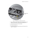
2. Use a #1 Phillips-head screwdriver to loosen the two screws on the
plastic cover over the positive and negative terminals on the power
supply and slide the cover to the right, as shown in Figure 126 on page
169. You may need to lift the locking handle slightly to access the
bottom screw.
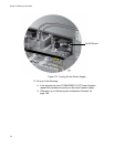
3. Use a #3 Phillips-head screwdriver to remove the two screws from the
positive and negative terminals, as shown in Figure 127 on page 170.
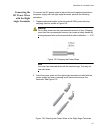
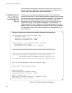
4. Wrap the positive lead wire clockwise around one of the terminal
screws and secure the screw and wire to the positive terminal
connection on the terminal block with a #3 Phillips-head screwdriver.
The positive terminal is on the left. You may attach the wire to the
terminal so that it extends either above or below the terminal block.
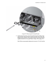
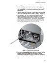
Figure 140 shows the wire above the terminal block. Allied Telesis
recommends tightening the screw to 30 to 40 inch-lbs.
Figure 140. Connecting the Positive Wire
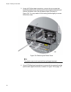
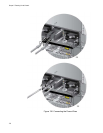
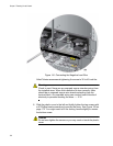
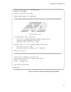
5. Wrap the negative lead wire clockwise around the remaining terminal
screw and secure the screw and wire to the negative terminal
connection on the terminal block with a #3 Phillips-head screwdriver,
as shown in Figure 141 on page 182. The negative terminal is on the
right.