


AT-x210-9GT, AT-x210-16GT, and AT-x210-24GT Switches Installation Guide
13
LEDs
There are four types of LEDs on the AT-x210 switches:
“POWER/FAULT/STANDBY LEDs” on page 13
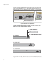
“10Base-T/100Base-TX/1000 Base-T Link Activity LEDs” on page 15
“SFP LEDs” on page 17
POWER/
FAULT/
STANDBY LEDs
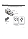
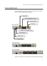
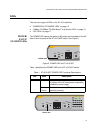
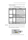
The POWER LED reports the status of AC power and is located on the left
side of the front panel of the AT-x210-9GT switch. See Figure 5.
Figure 5. POWER LED on AT-x210-9GT
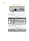
Table 1 describes the POWER LED for the AT-x210-9GT switch.
Table 1. AT-x210-9GT POWER LED Functional Descriptions
LED State Description
POWER Off Indicates either the switch is not receiving
AC power or the AC input power is operating
outside the normal range.
Steady
Green
The switch is receiving AC input power and is
operating normally.
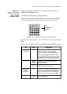
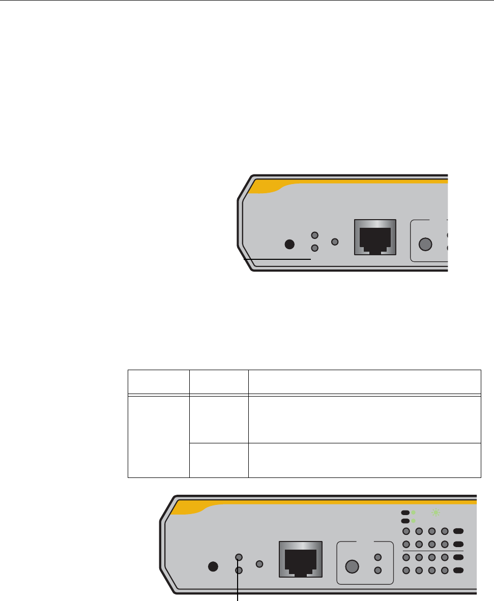
FAULT
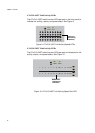
STANDBY
RESET
POWER
CONSOLE
RS-232
MODE
SP
DU
SELECT
POWER LED
FAULT
STANDBY
RESET
POWER
CONSOLE
RS-232
MODE
SPEED
DUPLEX
SELECT
2468
1357
L/A
MODE
L/A
MODE
MODE
SPEED / DUPLEX
L/A
LINK / ACT
FAULT LED