


Chapter 1: Overview
14
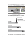
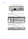
Figure 6. FAULT LED on AT-x210-9GT
Table 2 describes the functions for the FAULT LED for the AT-x210-9GT
and AT-x210-16GT switches.
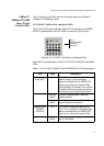
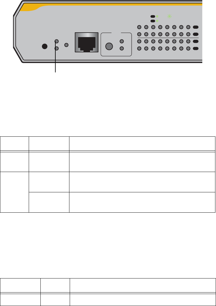
Table 2. AT-x210-16GT and AT-x210-24GT FAULT LED Functional
Descriptions
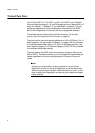
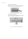
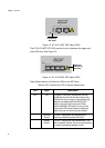
Figure 7. FAULT LED on AT-x210-16GT
Table 3 describes the functions for the STANDBY LED for the AT-x210-
9GT and AT-x210-16GT switches.
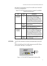
Table 3. AT-x210-16GT and AT-x210-24GT STANDBY LED Functional
Descriptions
LED State Description
FAULT Off The switch is receiving AC input power and is
operating normally
6 flashes in
2 seconds
Flashing indicates the switch is overheating.
Contact Allied Telesis for support and advice.
Steady
Green
Indicates the system is experiencing failure.
LED State Description
STANDBY Off STANDBY is not supported. The LED is not lit.
FAULT
STANDBY
RESET
POWER
CONSOLE
RS-232
SELECT
SPEED
DUPLEX
2 4 6 8 10 12 14 16R
13579111315R
L/A
MODE
L/A
MODE
MODE
SPEED / DUPLEX
L/A
LINK / ACT
MODE
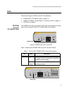
FAULT LED