


11
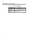
Table 1. Safety Symbols .....................................................................................................................................................16
Table 2. 10/100/1000Base-T Ports Matched with SFP Slots ..............................................................................................30
Table 3. Non-PoE Switch Base-T LED Descriptions ..........................................................................................................33
Table 4. SFP Slot LED Descriptions ...................................................................................................................................35
Table 5. XFP Slot LED .......................................................................................................................................................35
Table 6. System STATUS LEDs .........................................................................................................................................36
Table 7. STACK LEDs ........................................................................................................................................................38
Table 8. Secure Digital LED ...............................................................................................................................................39
Table 9. IEEE 802.3af Class vs. Power Levels ..................................................................................................................42
Table 10. Stacking Compatibility by Product Type .............................................................................................................50
Table 11. State Change Table ............................................................................................................................................53
Table 12. Stacking LED Functions .....................................................................................................................................58
Table 13. Twisted Pair Cabling and Distances ...................................................................................................................78
Table 14. MDI Pin Signals - 10 or 100 Mbps ....................................................................................................................104
Table 15. MDI-X Pin Signals - 10 or 100 Mbps ................................................................................................................104
Table 16. Pin Signals - 1000 Mbps ...................................................................................................................................105
Table 17. RJ-45 Style Serial Terminal Port Pin Signals ...................................................................................................106
Table 18. AT-RPS3104 17-Pin Connector Pinout Definitions ...........................................................................................107
Table 19. AT-RPS3204 21-pin Connector Pinout Definitions ...........................................................................................108
List of Tables