


Chapter 1: Overview
42
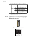
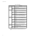
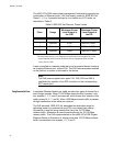
The x600-24Ts-POE smart power management functionality supports any
combination of Ethernet ports (1-24) that supply power for IEEE 802.3af
Class 0, 1, 2, or 3 powered devices up to a maximum of 370 watts, as
described in Table 9.
*
The Maximum Power Level Output levels reflect the loss introduced by a 100
meter Ethernet cable between the Power Source Equipment (PSE) and the
Power Device (PD).
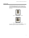
A port connected to a network node that is not a powered device functions
as a regular Ethernet port, without PoE. The PoE feature remains enabled
on the port but no power is delivered to the device.
Note
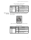
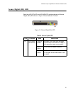
The PoE power supplied from ports 21R, 22R, 23R and 24R is
unaffected by insertion of an SFP module in to the corresponding
SFP combo port.
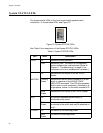
Implementation A standard Ethernet twisted pair cable contains four pairs of strands for a
total of eight strands. When 10/100 Mbps network traffic is present, only
four strands (1, 2, 3, and 6) are required, which leaves four strands in the
cable unused (4, 5, 7, and 8). When 1000 Mbps network traffic is present,
all eight conductors in the cable are required.
The PoE standard, IEEE 802.3af, describes two alternative ways for
delivering power to a powered device (PD) over twisted pair cabling.
Alternative A uses the same strands that carry the 10/100 Mbps
network traffic. Alternative B uses the spare strands for 10/100 Mbps
network traffic. The PoE implementation on the x600-24Ts-POE Gigabit
Ethernet Switch is Alternative A, where power and 10/100 Mbps network
traffic is transmitted over strands 1, 2, 3, and 6.
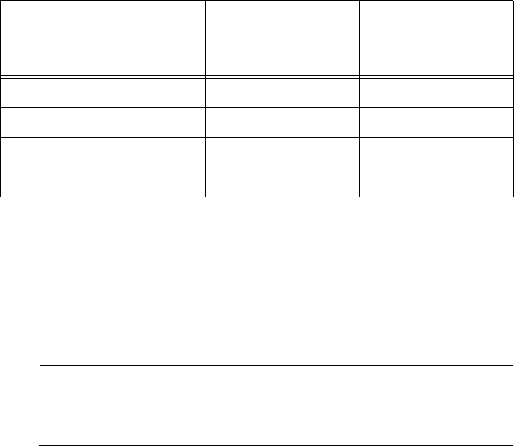
Table 9. IEEE 802.3af Class vs. Power Levels
Class Usage
Maximum Power
Level Output at
the PSE
Maximum Power
Level Output at
the PD
*
0 Default 15.4W 0.44W to 12.95W
1 Optional 4.0W 0.44W to 3.84W
2 Optional 7.0W 3.84W to 6.49W
3 Optional 15.4W 6.49W to 12.95W