


MULTITASKER
400-0402-003
5
APPLICATION DIAGRAMS 5
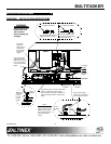
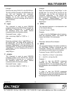
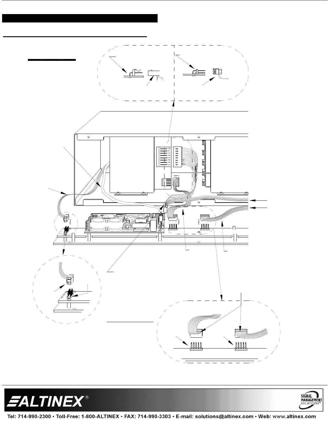
DIAGRAM 1 – INSTALLATION INSTRUCTIONS
POWER SUPPLY
Make sure
the ribbon
cable is
on this
side as
shown.
10-PIN
HEADER
P4
TO PCB-A
TO PCB-B
10-PIN
HEADER
P3
10-PIN
HEADER
P1
Make sure the ribbon
cables are on this side of
the connector as shown.
TO PCB-A
SIGNAL
Connect the
signal cable
to PCB-A.
Connect the
signal cable
to PCB-B.
Connect the 10-pin connector of the power
supply "Y" cable to the power supply.
Next, connect the two 8-pin connectors to
enclosure headers PCB-A and PCB-B as
shown.
Connect power from the power
supply connector as shown.
LARGE 8-PIN HEADER
on PCB-A and PCB-B
Connect the ribbon
cable from the rear
DB9 connector on the
rear of the enclosure
to the front panel PC
board.
Connect the
AC power
cable from the
rear panel of
the enclosure
to the power
supply.
TO PCB-A
POWER
PCB-B
PCB-A
Connect the signal cable
connector from front panel
PC board as shown.
POWER SUPPLY
FRONT PANEL PC BOARD
SMALL 10-PIN HEADER
on PCB-A and PCB-B
Disconnect the AC
power cord from
the enclosure
before making any
changes.
WARNING
On some versions, P3 is
slightly under the power
supply card. The cable
can be installed without
removing the power
supply.
NOTE