


MULTITASKER
400-0402-003
7
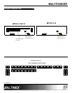
INSTALLING YOUR MT101-114/115/117 6
Step 1. Turn off power to the MultiTasker
enclosure and disconnect from AC power.
WARNING! ALWAYS DISCONNECT
THE AC POWER CORD BEFORE
OPENING THE ENCLOSURE.
Step 2. The electronic components inside the
enclosure and front panel are
static-sensitive. Please take precautions
to avoid electrostatic discharge (ESD).
Step 3. Remove the 6 screws on the front panel
to access the cables inside the enclosure.
Avoid handling the panel by the circuit
boards; handle by the metal panel only.
Step 4. Follow the connector orientation
illustrations shown in the Installation
Instructions on page 5.
CAUTION! Avoid possible electrical
damage by ensuring that all header pins
are aligned properly before restoring
power.
Step 5. After connecting the cables, fasten the
panel to the enclosure with the 6 screws
removed previously. Be careful not to
pinch any cable between the panel and
the enclosure.
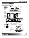
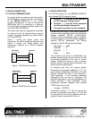
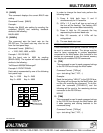
Step 6. If a PC or control system is used to control
the cards in the MultiTasker, connect the
9-pin D connector of the
MT101-114/115/117 to the control
system’s RS-232 port.
MultiTasker
Computer/
Control System
GND (Ground) Ground
RXD (Receive) Transmit
TXD (Transmit) Receive
Step 7. Turn on the power switch of the
MT101-114/115/117 MultiTasker. The unit
is now operational.
OPERATION 7
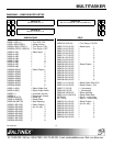
The key programs and subroutines described in
this section may be programmed on-the-fly or
saved in a text file and downloaded to the
MultiTasker using communication software such as
MTSetup or AVSnap
®
. The sample program file
shown in DIAGRAM 2 is a simple matrix control
including volume control for an audio card. Use this
example to see how keys and subroutines are
typically programmed and organized.
7.1 TERMINOLOGY
The terms below are used to increase the legibility
of the descriptions used in this section of the
manual.
Cn This term refers to a MultiTasker card
where the ID number is n. Typically, “n”
is the slot number of the card, but may
also be an assigned value. Example:
C1, C2, C3, etc.
Gk This term refers to a group of cards
where “k” is the group number. Groups
are defined using the write group
command [WR]. The possible groups
are G1-G8.
Ui This term refers to the ID number of a
MultiTasker enclosure. The value of “i”
may be a value from 0 to 20 where 0 is
the default value in single MultiTasker
systems.
string A string is one or more text characters
that form a command, describe output
data, or refer to incoming feedback.
feedback Feedback refers to text data that is
received from the MultiTasker or any of
the cards installed in the enclosure.
Sub This term is an abbreviated form for
subroutine. A subroutine is a section of
memory used to store commands that
control the cards within the enclosure.
Example: SUB1, SUB2, etc.