


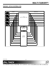
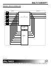

MULTI-TASKER™
400-0362-003
14
14. […P] – PATH
This command will set the path for the output,
but it is not active until the switch command,
[SW], is executed. Commands ending in "P" are
not executed immediately. The path for outputs
on multiple cards or the same card can be
preloaded. See the examples in the ON and
OFF command descriptions.
Example:
There is an MT105-120 in slot #4. Currently,
Input 1 is connected to all outputs and all
outputs are ON. The PATH command has been
used to set Input 2 to Output 1 and turn OFF
Outputs 2 and 3 at the same time. If checking
the status prior to sending the [SW] command,
the feedback will appear as follows for the
above connection settings:
In1-Out1 ON P=2
In1-Out2 ON P=OFF
In1-Out3 ON P=OFF
In1-Out4 ON
In1-Out5 ON
In1-Out6 ON
In1-Out7 ON
The notation "P=" at the end of the line
indicates the path condition is active. "P=2" on
the Output 1 line indicates that after the [SW]
command, Input 2 will be connected to Output
1.
The notation "P=OFF" on lines 2 and 3
indicates that Outputs 2 and 3 will be turned
OFF after the [SW] command is executed.
15. [SW] – SWITCH
This command immediately connects inputs
and outputs previously set with the PATH
command. The command switches all paths
set on this card and all other cards in the
enclosure.
Example:
The following commands set the path for
turning ON Output 1 of the card in slot #6 and
turning OFF Output 3 of the card in slot #7.
Nothing happens until the [SW] command is
sent. At that time, Output 1 will be enabled and
Output 3 will be disabled.
[ON1C6P]
[OFF3C7P]
[SW]
16. [IO]
This command will connect a single input with
one or all outputs. It will not effect the ON/OFF
status of the output.
Command Format: [IxOyCnUi]
x = Input (x = # from 1 to max inputs)
y = Output (y = # from 1 to max, or [ for all)
Cn = Card ID (n = # from 1 to max slots)
Ui = Unit ID (i = # from 0 to 9)
Example:
An MT105-120 is in slot #4 Connect Input 1 to
all outputs by sending the command [I1O[C4].
After the command is sent, Input 1 will be
connected to all outputs. In order to turn ON all
the outputs, send the command [ONC4].
17. [CLR]
This command resets the card configuration to
the factory defaults. After the [CLR] command,
Input 1 will be connected to all outputs and all
outputs will be ON.
Command Format: [CLRCnUi]
Cn = Card ID (n = # from 1 to max slots)
Ui = Unit ID (i = # from 0 to 9)
Example:
Send the command [CLRC4] to reset the card
in slot #4 to its factory defaults.