


MULTI-TASKER
7
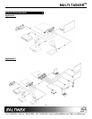
INSTALLING YOUR MT106-101 6
Step 1. Slide the MT106-101 into an available slot
in the Multi-Tasker™ Basic Enclosure in
order to connect to the bus. Make sure
that the MT106-101 Scan Doubler card
fits into place. Secure the card to the
Multi-Tasker™ by tightening the retainer
screws located on the top and bottom of
the MT106-101 Scan Doubler card.
Step 2. The LED on the card panel will turn red
indicating that the card is in full operation.
A green LED indicates that an input signal
is present. An LED that is blinking red
indicates that the card is experiencing a
problem. If the LED is blinking, see the
Troubleshooting Guide in section 10.
Step 3. Connect an S-Video cable or C-Video
cable (coaxial cable) from the video
source to the input connectors of the
MT106-101. Connect the output
connector of the MT106-101 to the
display device through a VGA cable.
Step 4. Starting from the left, identify the slot
number where the MT106-101 card is
plugged into the Enclosure. Note that the
slot number is required for RS-232
control.
OPERATION 7
7.1 RS-232 CONTROL
When used in the Multi-Tasker™ Basic
Enclosure, the MT106-101 has many advanced
remote control capabilities, which are accessible
through standard RS-232 communication. The
actual control may be accomplished through a
computer control system or any other device
capable of sending RS-232 commands.
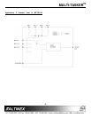
7.1.1 RS-232 INTERFACE
The RS-232 commands for the MT106-101 are
in a simple ASCII character format.
1. Square brackets “[ ]” are part of the
command.
2. Use uppercase letters for all commands.
After processing a command, an OK or ER
string will be returned as feedback if "F" is
included at the end of a command string or if
the unit ID is zero.
7.2 DESCRIPTION OF COMMANDS
Each command consists of three parts: function,
card ID, and unit ID. [Function, Card ID,
Unit ID].
Example:
[VERC3U2]
VER = Function
C3 = Card ID
U2 = Unit ID
For Function, see a detailed explanation under
each command description.
The Card ID is an assigned value from 1 to 19,
based on which slot the card is put in. The Card
ID 0 (C0) is used for the controller (see user’s
guide for the MT100-100). Changing the
position of a card will significantly affect the
commands recorded on software definitions or a
third party control system.
The Unit ID has a value from 0 to 9. The Unit
ID 0 should be used for single unit operation. If
the Unit ID is set to 0, then each command can
be used without Ui (use command [SETU0]; see
user’s guide for the MT100-100).
Example:
[VERC3]: for unit ID zero
[VERC3Ui]: for unit ID other than zero
[VERC3]: equivalent to [VERC3U0]
1. [VER]
This command displays the software version
and card type for the Scan Doubler card.
Command Format: [VERCnUi]
Cn = card ID No. (n = slot # from 1 to 19)