


MULTITASKER™
400-0095-005
7
7
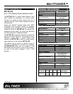
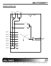
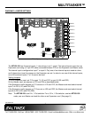
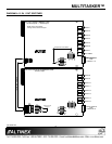
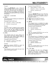
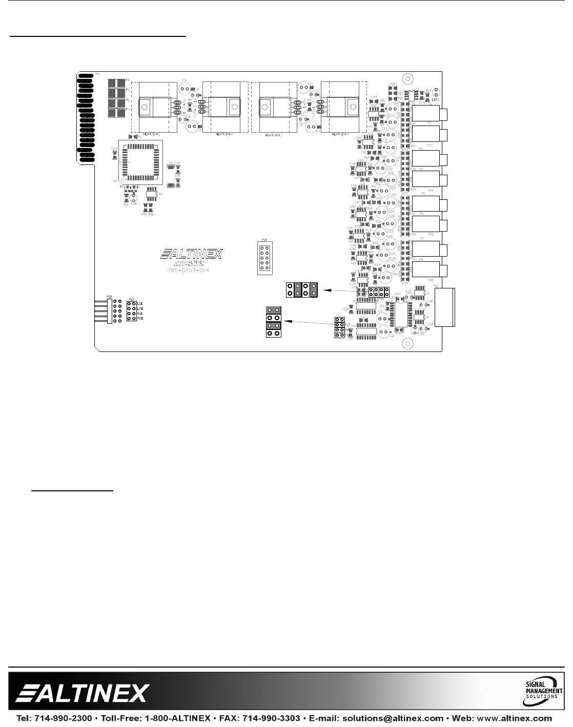
DIAGRAM 3: JUMPER SETTINGS
The MT109-100 has 8 external inputs, 1 internal input, and 1 output. The internal inputs come from an
Expansion card using a 10-pin IDC cable connected between P12s of the Expansion and Master cards.
The internal input is configured as input 7 or input 8. Only one of two internal inputs is used at a time
and it depends on how the jumpers on the Expansion are set. In order to use one of the internal inputs,
one of the external inputs (7 or 8) cannot be used.
Setting Jumpers:
1) As an Expansion card: set P13 as port 7 (L1E and R1E) or port 8 (L2E and R2E).
2) As a Master card: set jumpers on P23 and P24 as described below.
If the Expansion card's jumpers on P13 are set on L1E and R1E, the Master card must select internal
input 7 on P23 (L1E) and P24 (R1E).
If the Expansion card's jumpers on P13 are set on L2E and R2E, the Master card must select internal
input 8 on P23 (L2E) and P24 (R2E).
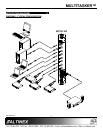
Note: The MT109-100 is an 8-In, 1-Out switcher. For a 15-In, 1-Out switcher, use two MT109-100
cards, one as a Master card and the other as an Expansion card. (See page 8.)
INPUT 1
INPUT 2
INPUT 3
INPUT 4
INPUT 5
INPUT 6
INPUT 7
OUTPUT
INPUT 8
P23
L2EL1E L7 L8
R2E
R7
R1E
R8
P24
R2E
R8
R1E
R7
P24
P23
L7L1E L2E L8
Default jumper settings shown.