


SWITCHERS
9
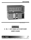
This command is designed to allow the MX2206RM
Switcher to program each of the inputs to respond
to a selected range of input commands.
For example, if command [SET10104] is issued,
then the following commands will select only Input
1: [I01O01], [I02O01], [I03O01], [I04O01]. In other
words a range of I/O commands can address the
same input. Default settings for each of the inputs
is as follows: Input 10101, Input 20202, Input
30303, Input 40404, Input 50505, & Input 60606.
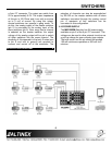
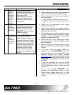
7.3 MASTER-SLAVE CONFIGURATION
These feedback codes allow multiple MX2206RM
Switchers to be connected in a Master-Slave
configuration, if desired.
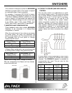
When the control ports of two units are connected
as shown below, the slave unit duplicates the
actions of the master unit. The same unit can still
be controlled from its front panel or through
another RS-232 control.
MX2206RM 9-pin D
Master PIN No.
MX2206RM 9-pin D
Slave PIN No.
2 3
5 5
Master-Slave Control Port Connection
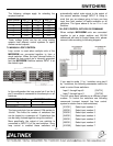
A Master-Slave configuration can be achieved also
by Analog Switch Voltage using pin#9 and pin#7.
MX2206RM 9-pin D
Master PIN No.
MX2206RM 9-pin D
Slave PIN No.
9 7
5 5
Master-Slave Analog Switch Voltage Connection
With this configuration the Master unit has ultimate
control over slave unit
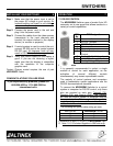
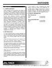
7.4 CONTACT CLOSURE (ONE WIRE ANALOG)
CONTROL
The one wire control is an alternative to a multi-
wire contact closure control. This control pin allows
you to select different channels based on the DC
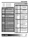
voltage level on pin 7 of the 9 pin D connector.
Internally, pin 7 is pooled up to 5 volts by a 10k
resistor. Thus, by selecting the proper resistor
values connected to ground any channel can be
selected. Although the channel selection by the
relay contact is latching and will maintain the last
relay-selected channel, it is recommended that
momentary contact closures not be used. Typical
resistor values and wires connections are shown
below.
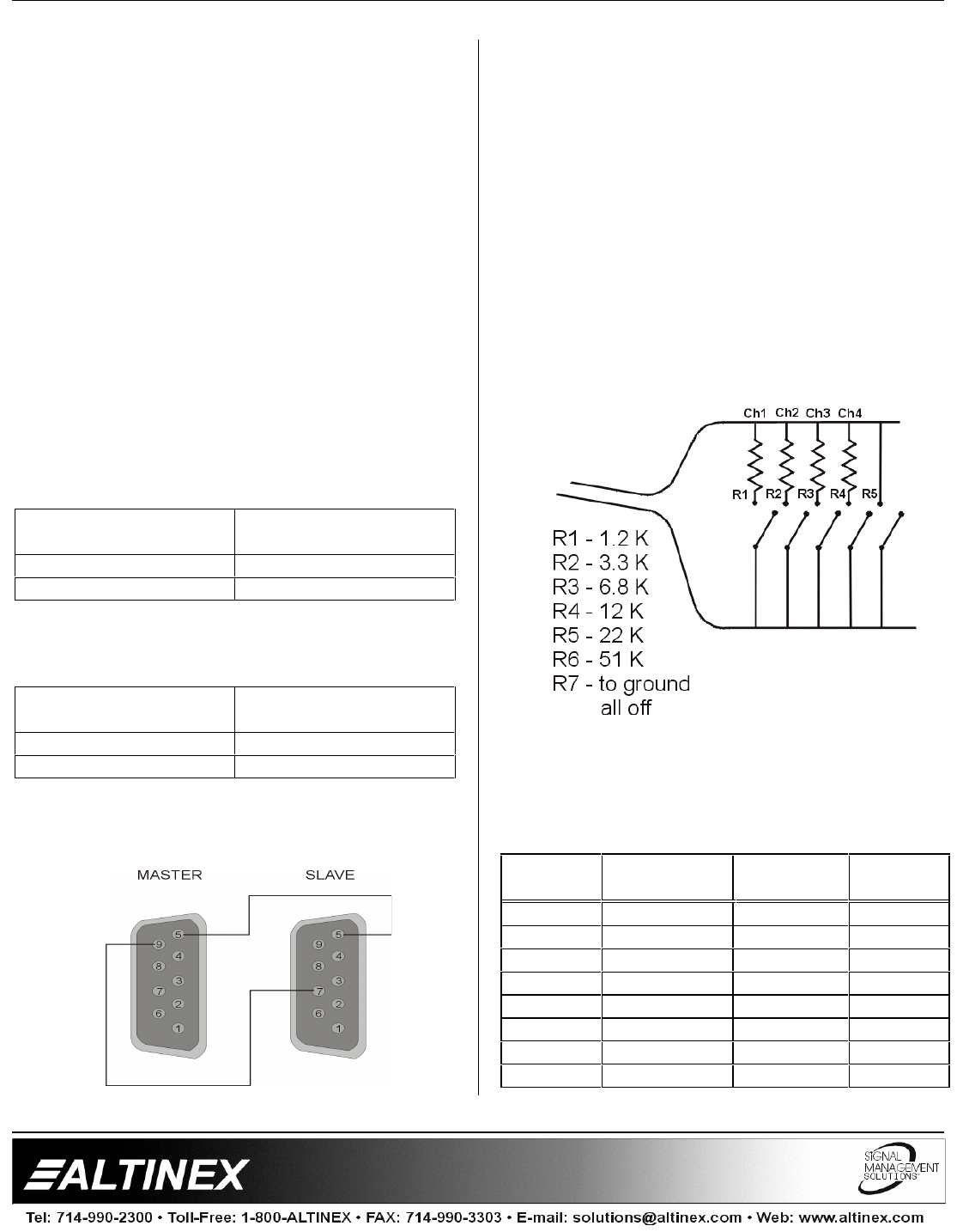
In some cases it may be preferable to use a seven
conductor wire to control the switcher with contact
closures. The RC5204CC adapter is available to
accommodate this need. The pin outs for this
adapter are as follows:
9 pin “D”
Male
Description 9 pin “D”
Female
Input
7 1.2K 1 1
7 3.3K 2 2
7 6.8K 3 3
7 12K 4 4
7 22K 5 5
7 51K 6 6
7 0 short 7 NONE
5 Ground 9