


SWITCHERS
10
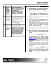
The following voltages apply for selecting the
required channel:
Input number min. (V) nom. (V) max. (V)
1 0.35 0.55 0.75
2 1.07 1.27 1.47
3 1.80 2.00 2.20
4 2.52 2.72 2.92
5 3.25 3.45 3.65
6 3.97 4.17 4.37
These voltage levels can be set using analog
outputs from different control systems or spare
dimmer control outputs.
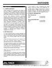
7.5 MANUAL LOOP CONTROL
Loop control is used when multiple units of the
MX2206RM are connected together to form a
single switcher. When the input channel button is
pressed the loop control pin is internally grounded
and the MX2206RM Switcher selects INPUT 4 as
the default input.
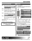
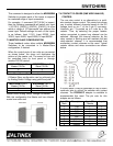
In this configuration the loop control pin 6 on the 9
pin D connector is connected to the same pin on all
switchers.
MX2206RM LOOP MX2206RM LOOP
6 6
5 5
MX2206RM 9-pin “D” Loop
The loop control pin has an internal 100k resistor to
+5volts. This limits the number of switchers that
can be looped to a maximum of 10 switchers that
can be daisy chained together using this method.
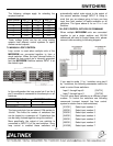
More specifically, the output of one switcher is
connected to INPUT 6 of the next switcher. Once
loop control is enabled these switchers will
automatically switch video signal to the output of
the second switcher through INPUT 6. Keep in
mind that you are always going to have one less
input then total number of inputs available on all
switchers. The figure above is for an 11-in 1-out
Switcher.
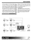
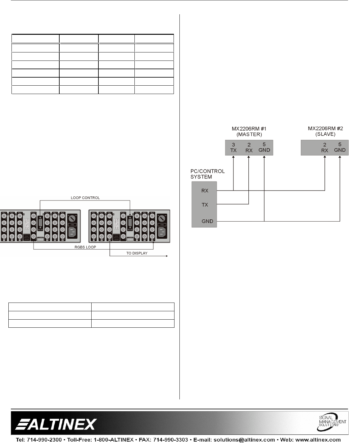
7.6 LOOP CONTROL WITH RS-232 COMMAND
When multiple MX2206RM units are connected
together to get a single switcher and RS-232
commands are used to control these units, please
connect units according to following diagram.
If you want to make 11 by 1 switcher using two 6
by 1 switchers, the following commands need to be
used to control these switchers:
Input 1 through Input 6 [OUT01]
Input 7 through Input 11 [OUT02]
This will setup each switcher as a different output
number. To control the switchers use following
commands (connect transmit line from control
system to receive line on both switchers):
[I01O01] Select input number 1
[I02O01] Select input number 2
[I03O01] Select input number 3
[I04O01] Select input number 4
[I05O01] Select input number 5
[I06O01] Select input number 6
[I01O02] Select input number 7