


SWITCHERS
6
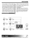
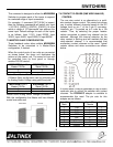
a 9-pin “D” connector. The output can switch from
0V to approximately 5.0V. The output impedance
of this pin is 100 Ohms and it can sink or source
up to 5 mA of current. By using this output,
several switchers can operate in gang mode. To
do this, the analog output of the master switcher
(pin 9) is connected to the analog input of the
slave switchers (pin 9). Now, every time a channel
is selected on the master switcher, the output
voltage of the analog output will be set to switch
all other switchers into the same channel. The
simplicity of this approach is that only 2 wires (one
to pin 9 and one to ground) are required to
connect and control all of the switchers. The
selection of channels can also be accomplished
by RS-232 on the master switcher with all slave
switchers connected through the analog control
pin. A maximum of four switchers can be
connected in this configuration.
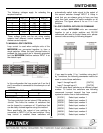
4.10 POWER SUPPLY
The MX2206RM Switcher has 5V power supply
available on pin 8 of the 9-pin “D” connector. This
voltage can be used to drive external circuits or as
a pull up voltage for open collector type outputs.
The total current on this pin should not exceed
150 mA continuous operation or 500 mA for 5
minutes.
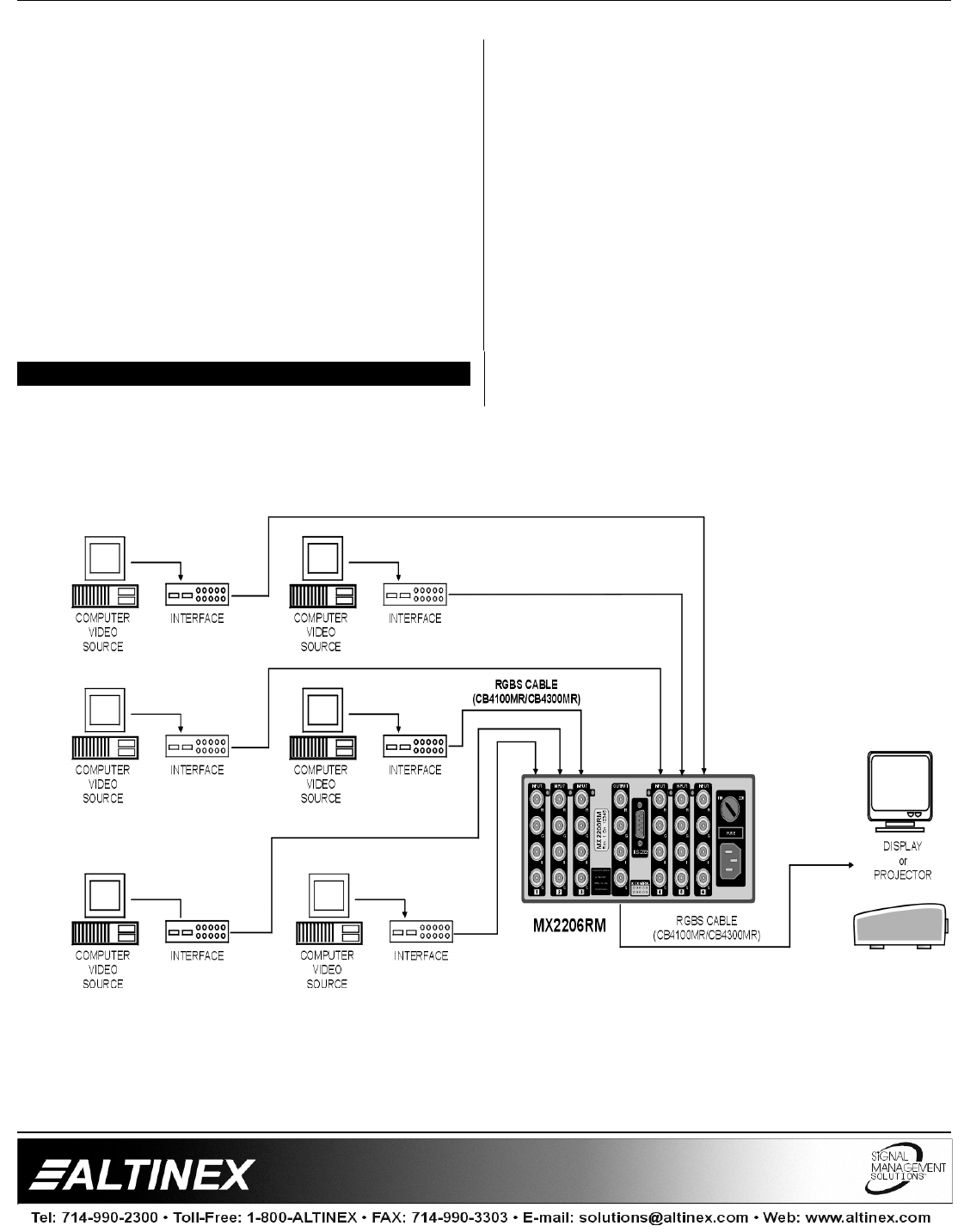
APPLICATION DIAGRAM 5