


SWITCHERS
6
beeping sound. If the unit is turned off and turned
back on, the LED of the selected channel should
light.
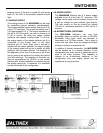
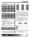
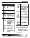
4.7 ANALOG OUTPUT
The analog output of the
MX2406RM
can be used
for controlling several switchers simultaneously.
The analog amplifier drives analog output pin 9 on
a 9-pin “D” connector. The output can swing from 0
V to approximately 5.0 V. The output impedance of
this pin is 100 Ohms and it can sink or source up to
5 mA of current. By using this output, several
switchers can operate in gang mode. To do this,
the analog output of the master switcher (pin 9) is
connected to the analog input of the slave
switchers (pin 9). Now, every time a channel is
selected on the master switcher, the output voltage
of the analog output will be set to switch all other
switchers into the same channel. The simplicity of
this approach is that only 2 wires (one to pin 9 and
one to ground) are required to connect and control
all of the switchers. The selection of channels can
also be accomplished by RS-232 on the master
switcher with all slave switchers connected through
the analog control pin. A maximum of 4 switchers
can be connected in this configuration.
APPLICATION DIAGRAM 5
4.8 POWER SUPPLY
The
MX2406RM
Switcher has 5 V power supply
available on pin 8 of the 9-pin “D” connector. This
voltage can be used to drive external circuits or as
a pull up voltage for open collector type outputs.
The total current on this pin should not exceed
150 mA of continuous operation or 500 mA for 5
minutes.
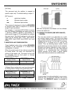
4.9 BI-DIRECTIONAL SWITCHING
The
MX2406RM
Switchers use very high
bandwidth relays to provide you with a 400 MHz
bandwidth. Each input, when not selected, is
terminated to a 75-Ohms resistor. This is done to
make sure that video lines are always terminated
whether a channel is selected or not.
In addition to forward connection, the
MX2406RM
can be hooked up in a reverse direction. In this
configuration one video source is selectively sent to
each of the video monitors. This capability is
referred to as bi-directional switching. In this
configuration only one display device can be
operational at any given time.