


SWITCHERS
7
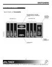
INSTALLING YOUR SWITCHER 6
Step 1
. Make sure that the power input is set to
the proper AC voltage in your country. An
incorrect setting can result in unit damage
not covered by warranty.
Step 2.
Connect the power cord to the unit and
plug it into the power outlet.
Step 3.
Connect the cables from the video sources
(computers) to the input channels and
connect the output channel to the display
device (i.e. monitor or projector)
Step 4.
If a control system is used to control the
unit connect RS-232 port to the control
system’s RS-232 card. An improper hook
up may result in RS-232 interface damage.
Step 5.
Verify that the picture quality on the display
is good. If you are not receiving a signal,
make sure that the display is compatible
with the resolution of the computer
graphics card.
Contact Closure control requires the use of part #
RC5204CC
Cable.
CONGRATULATIONS! YOU ARE DONE.
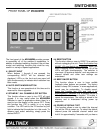
OPERATION 7
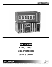
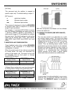
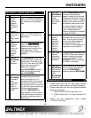
7.1 RS-232 CONTROL
The
MX2406RM
Switcher uses a female 9-pin HD
connector on its rear panel that allows access to a
variety of control capabilities.
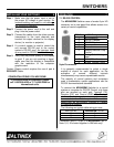
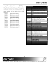
PIN No. PIN Designation
1 No connection
2 RS-232 Transmit
3 RS-232 Receive
4 No connection
5 Ground
6 Multiple Switcher Loop
Control
7 Analog Switch Voltage
Input
8 +5 V (150 mA max)
9 Analog Voltage Output
9-pin D connector
It is generally recommended to select a single
method of control for each application, as the
activation of several different controls
simultaneously may cause unpredictable results.
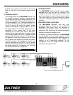
The majority of control systems and computers
used in presentation system applications use the
RS-232 communications standard.
To connect the
MX2406RM
Switcher to a control
system or computer for RS-232 Control, only three
pins are required on each port: Transmit (TX),
Receive (RX), and Ground (GND). The Transmit
pin from the control system or computer must be
connected to the Receive pin of the switcher
control port; do not connect Transmit to Transmit
or Receive to Receive.
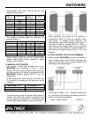
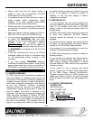
The following are typical cable wiring pin outs:
IBM PIN No.
MX2406RM
PIN No.
32
23
75
Connection IBM-PC 25-pin D to
MX2406RM
9-pin D
Note: 5, 6, 20 shorted together in IBM side only.
If you experience any problems, please
call 1-800-258-4623 or 1-714-990-2300 for
international calls.