


ACCESSORIES
3
equipment in a residential area is likely to
cause harmful interference in which case
the user will be required to correct the
interference at his own expense.
• Any changes or modifications to the unit not
expressly approved by ALTINEX, Inc. could
void the user’s authority to operate the
equipment.
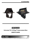
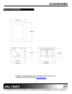
ABOUT YOUR TNP500/502 2
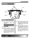
The TNP500 designed for installation into a table in a
presentation or boardroom, the Tilt `N Plug™
Configurable Tabletop Interconnect Box provides
access to multi-media input connections when
needed, and hides them when not needed. This unit
can be configured with a wide variety of data or A/V
connectors before shipment from ALTINEX.
Using a tilting angular construction with pneumatic lift
assist and a mechanical latching mechanism, the
TNP500 can either "tilt up" into a raised position to
provide access to input plates, or it can be lowered
flush into the table when not in use. The unit is
opened and closed by pressing down on the top
panel.
Note that, while the TNP500 is similar in many ways
to its predecessor (TNP100), it actually performs the
lifting function internally, and does not require the user
to lift the faceplate up. Only light pressure is required
to unlatch the top to open it, and slightly more
pressure to push the lid down and close the unit.
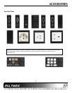
The TNP500 provides six Sectional Plate slots on the
exposed faceplate, servicing one side of a table.
Signals are passed through the unit to the underside
of the table. A variety of sectional plate connector
configurations are available to populate the slots - see
Sectional Plate Accessories for a list of available
options. All Sectional Plates must be ordered
separately.
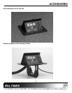
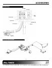
The TNP502 is a "package" of parts that covers the
basic needs of many Tilt ‘N Plug users. When this
item is ordered, it ships as a completely assembled
product made up of: one TNP500 and a SP3500SC
Sectional Plate, with input labels already engraved
The SP3500SC includes the following connectors:
two standard U.S. power receptacles, computer video
(15-pin HD), COM Port/RS-232 (9-pin D), composite
video (RCA), S-Video (4-pin mini-DIN), audio (2-
RCAs), computer audio (3.5 mm), modem (RJ11),
and network (RJ45) input connectors. All connectors
have 6 foot cables attached that feed through to the
bottom of the unit. The connectors and their labels
may be customized for a fee.
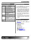
TECHNICAL SPECIFICATIONS 3
FEATURES/
DESCRIPTION
TNP502
GENERAL
Front Panel
Standard
Configuration
Connectors
Faceplate
Available
location
Power
2 outlet per plate
Up to 3 plates
Computer Video 1 15-pin HD-F Up to 6 plates
Composite Video 1 Yellow RCA-F Up to 6 plates
Audio, left, right 1 Black, 1 Red
RCA-F
Up to 6 plates
Audio 1 3.5 mm stereo
female plug
Up to 6 plates
Telephone 1 RJ-11 F (6-
position)
Up to 6 plates
Network 1 RJ-45-F (8-
position)
Up to 6 plates
Control 1 DB-9 F Up to 6 plates
Table 1. TNP502 General
MECHANICAL TNP500/502
Width (inches) 6.03in (153mm)
Height (closed) 4.79in (122mm)
Height (opened) 8.05in (205mm)
Depth (inches) 7.56in (192mm)
Finish Flat Black
T° Operating 10°C-45°C
T° Maximum 60°C
Humidity
90% non-condensing
Table 2. TNP500/502 Mechanical
ELECTRICAL TNP502
Power
Power Rating (pass through
connector)
90-140 VAC, 5Amps
Max
Table 3. TNP502 Electrical