


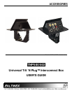
ACCESSORIES
8
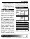
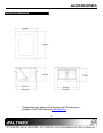
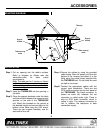
MOUNTING DIAGRAM 7
INSTALLATION 88
Step 1. Cut an opening into the table’s surface.
Refer to diagram on Altinex web site
www.altinex.com for table cutout
requirement s.
Note: The table can be 3 inches or thinner
in thickness. Always confirm dimensions
before cutting to insure that specifications
have not changed.
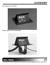
Step 2. Insert the TNP500/502 into the opening in
the table.
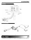
Step 3. Place the support brackets under the table
and place them between the support mount
grooves on the side of the TNP500/502
unit. Attach the brackets to the groove at
the desired height and secure them to the
bottom of the table using the 6-32 screw.
There are two support brackets, one for
each side of the unit.
Step 4 Secure the cables by using the provided
cable clamp. Pass the power cord from the
bottom of the housing and attach it to the
table using the cable clamp supplied with
the TNP500/502 unit. Do not keep the cord
too tight or too loose.
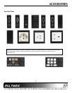
Step5 Connect the appropriate cables with the
correct input connectors. There are two
RCA audio connectors on the front panel of
the TNP500/502. The black connector is
known as audio left, whereas the red
connector is called audio right. There is
also an RCA video connector, which is
yellow in color. The network connection is
red. In addition, the telephone or data
connection is gray.
Support
bracket
Support
bracket
Table securing
screw
Table securing
screw
Table top