


Chapter 1. Installing an AMCC 3ware 9550SX RAID Controller
18 3ware 9550SX Serial ATA RAID Controller Quick Install Guide
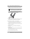
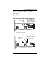
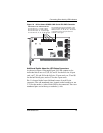
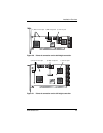
Note: The LED headers on the 9550SX-12 and the 9550SX-12MI
are in a very similar place.
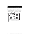
Figure 17. 12-Port 3ware 9550SX-12 Serial ATA RAID Controller
Overall LED drive status indicator is the
right-most LED header pin pair on each
LED connector (J7, J8, and J9). The
anode is the lower of the two pins and
the cathode is the upper.
LED indicators for individual drives
J7 is for drives 0, 1, 2, 3 (left to right)
J8 is for drives 4, 5, 6, 7 (left to right)
J9 is for drives 8, 9, 10, 11 (left to right)