


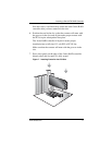
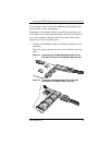
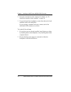
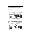

Connecting Drive Activity LED Indicators
www.3ware.com 19
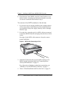
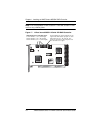
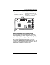
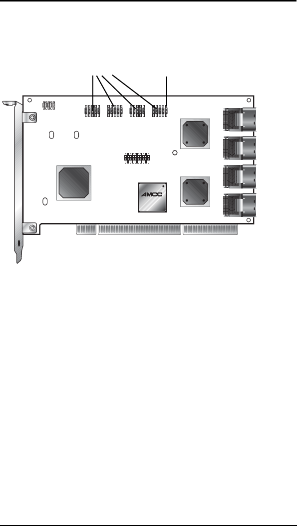
Figure 18. 16-Port 3ware 9550SX-16ML Serial ATA RAID Controller
Additional Details About the LED Status Connectors
As shown in Figure 15 through Figure 18, LED connectors for
individual drives are on J7, J8, J9, and J1 for the full-size 16 port
card, on J7, J8, and J9 for the full-size 12-port cards, on J7 and J8
for the half-size 8-port, and on J7 for the 4-port cards.
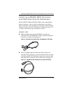
Pin 1 is located in the lower left-hand corner of each 10-pin
connector. The odd-numbered pins, located on the bottom row, are
3.3V for the anode (+) side of each LED to be connected. The even-
numbered pins are on the top or cathode (-) side.
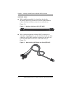
Overall LED drive status indicator is the
right-most LED header pin pair on each
LED connector (J7, J8, J9, J1). The anode
is the lower of the two pins and the
cathode is the upper.
LED indicators for individual drives
J7 is for drives 0, 1, 2, 3 (left to right)
J8 is for drives 4, 5, 6, 7 (left to right)
J9 is for drives 8, 9, 10, 11 (left to right)
J1 is for drives 12, 13, 14, 15 (left to right)