


Chapter 1. Installing an AMCC 3ware 9550SX RAID Controller
20 3ware 9550SX Serial ATA RAID Controller Quick Install Guide
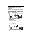
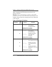
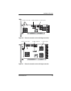
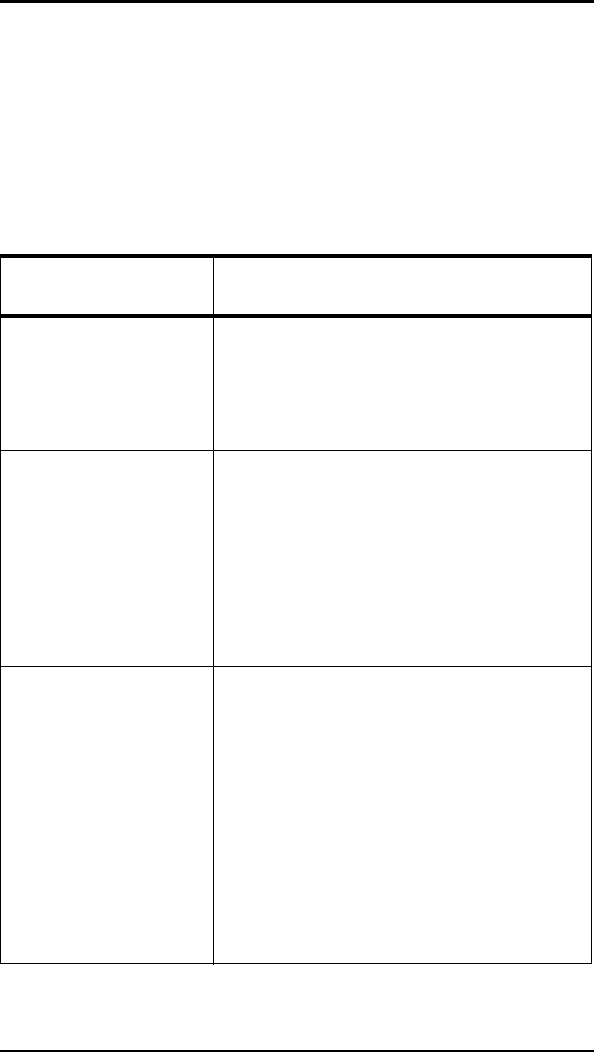
Table 1 summarizes the LED indicator pin positions for the
different controllers.
Warning: If using a chassis that has a common or shared LED
ground, be sure to only connect LED cables to the anode pins on the
controller. Do not connect any common ground to any cathode pins
on the controller.
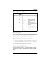
Table 1: LED Indicator Pin Positions
Controller
LED
Header
Pin Pair Comment
9550SX-4LP J7 : : : : : Orientation Horizontal
0 1 2 3 All Port number/All
(all activity indicator)
k-cathode-minus is on the top
a-anode-plus is on the bottom
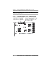
9550SX-8LP J7 : : : : : Orientation Horizontal
0 1 2 3 All Port number/All
(all activity indicator)
J8 : : : : : Orientation Horizontal
4 5 6 7 All Port number / NU
(Not Used)
k-cathode-minus is on the top
a-anode-plus is on the bottom
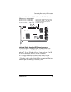
9550SX-12/12MI J7 : : : : : Orientation Horizontal
0 1 2 3 All Port number/NU (Not Used)
J8 : : : : : Orientation Horizontal
4 5 6 7 All Port number/NU (Not
Used)
J9 : : : : : Orientation Horizontal
8 9 10 11 All Port number/All (all activity
indicator)
k-cathode-minus is on the top
a-anode-plus is on the bottom