


Hardware Installation- 23 -
English
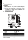
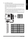
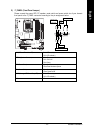
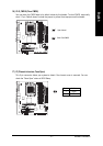
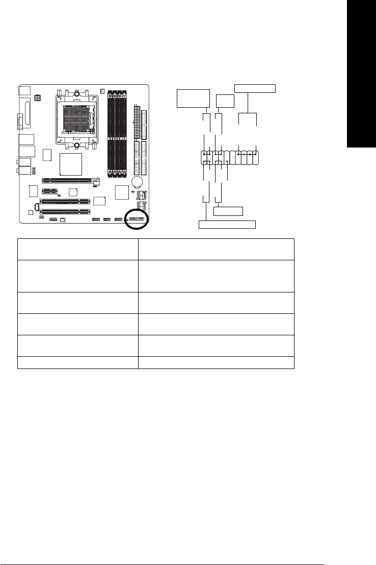
9) F_PANEL (Front Panel Jumper)
Please connect the power LED, PC speaker, reset switch and power switch etc of your chassis
front panel to the F_PANEL connector according to the pin assignment below.
HD (IDE Hard Disk Active LED) Pin 1: LED anode(+)
Pin 2: LED cathode(-)
SPEAK (Speaker Connector) Pin 1: Power
Pin 2- Pin 3: NC
Pin 4: Data(-)
RES (Reset Switch) Open: Normal
Close: Reset Hardware System
PW (Power Switch) Open: Normal
Close: Power On/Off
MSG (Message LED/Power/Sleep LED) Pin 1: LED anode(+)
Pin 2: LED cathode(-)
NC NC
1
2
19
20
HD-
HD+
RES+
RES-
NC
IDE Hard Disk Active LED
Reset Switch
SPEAK-
MSG-
MSG+
PW-
PW+
Message LED/
Power/
Sleep LED
Speaker Connector
SPEAK+
Power
Switch