


©American Audio® - www.americanaudio.com - WM-16™ Instruction Manual Page 5
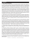
WM-16™ RECEIVER CONTROLS AND FUNCTIONS
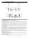
1. Antennas - Receives RF signals from the transmitter.
2. Power Indicator LED - This LED will indicate that the power is on.
3. AF Indicator LED - This LED will indicate when the clearest transmitter signal has been reached.
4. Diversity A & B Indicators - These LED’s indicate that the antennas are receiving an RF Signal.
5. 12v DC Input - Connect the included power supply to this input, or any other 12v power adapter.
6. Squelch Adjustment - The squelch adjusts the output level to prevent external noise. If you set
the squelch to high you will reduce the range of the system. Set the squelch to a minimum before
turning the receiver on.
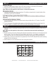
7. Channel Selector - Use these dipswitches to set your desired channel. Follow the dipswitch
chart on page 6 to set your desired channel. You must also set the Mic or Lavalier to same channel
as the receiver. Set the mic by by unscrewing the bottom half of the mic and setting the dipswitches
to the same channel. The Lavalier dipswitches are located on the side of the lavalier.
8. Mic/Line Switch - This switch lets you select your output source. If your connected to the line
input on a mixer or amplier set the switch to “Line”. If your connected to a Mic input on a mixer or
amplier set the switch to “Mic”.
9. Unbalanced 1/4” Output - This unbalanced output can be used to connect the receiver to the
line-level input of a mixer or amplier.
10. Balanced XLR Output - This balanced XLR output can be used to connect the receiver to bal-
anced input of mixer or amplier.
PWR
AF
A DIVERSITY B
AUDIO OUTPUT
BALANCED
UNBALANCED
LINE
CHANNEL
MIC
SQ
12V 500mA
DC INPUT
1 12 3 4
8910 7 6 5