Pegasus PCI Motherboard User’s Guide
8
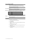
Step 5 Connect CPU Fan
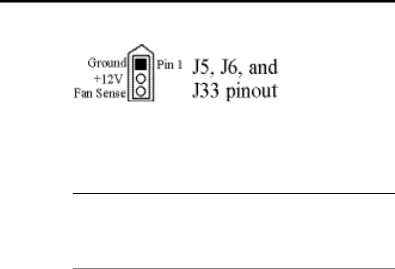
J6 (shown below) is a 3-pin berg that connects the fan on the CPU heat sink
to the motherboard power.
All Pentium II CPUs are shipped with a heat sink and a CPU fan. The
connector from the CPU fan usually has three leads (has red, yellow, and
black leads). Connect the Red lead to Pin 2 (+12V). Make sure that you use
fans that have 3 leads. The 3
rd
(yellow) lead should provide a tachometer
output to permit the fan speed to be monitored by the onboard server
management hardware. If you must use fans with only 2 leads, connect the
red lead to Pin 2.
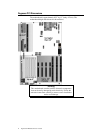
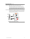
J5 and J33 Chassis Fans J5 and J33 are 3-pin bergs that attach to chassis fans. See the
motherboard drawing for the J5 and J33 locations. J5 provides +12V power to
the main chassis fan. J33 is the auxiliary chassis fan connector. He chassis
fan should provide a tachometer output on Pin 3 so the fan speed can be
monitored by the onboard server management hardware.


