Pegasus PCI Motherboard User’s Guide
12
Step 9 Attach Cables
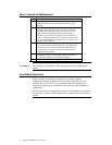
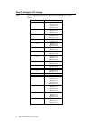
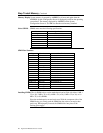
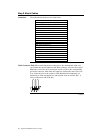
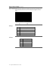
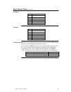
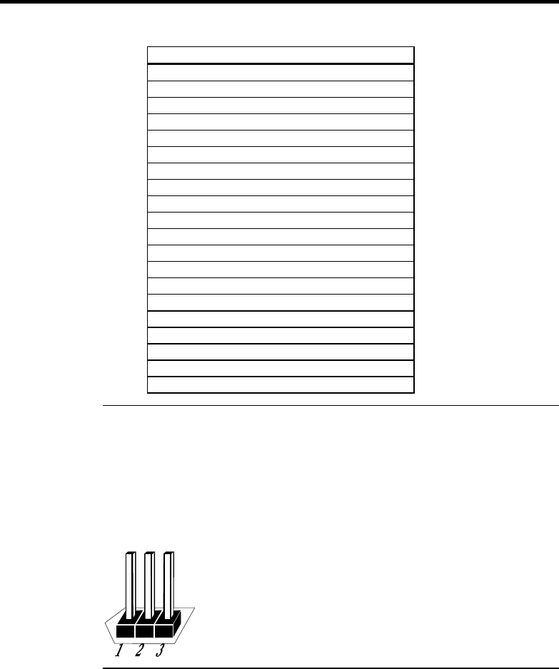
Connectors The motherboard connectors are listed below.
Connector
Power supply connectors P1, P2, P3, and P14
Drain CMOS RAM power – J29
Keyboard connector J10
PS/2 mouse connector J1
Chassis intrusion LED – J23
External SMI connector – J30
Hardware Reset switch J27
Speaker J32
Infrared connector to J34
Keyboard lock connector J25
Turbo LED connector J28
IDE LED connector J31
USB port 1 connector J15
USB port 2 connector J14
Serial port 1 connector J3
Serial port 2 connector J2
Parallel port connector J8
Floppy connector J4
IDE channel 0 connector J11
IDE channel 1 connector J9
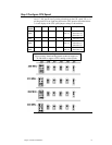
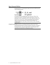
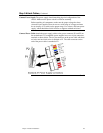
Cable Connector Ends When connecting chassis connectors to the motherboard, make sure
you connect the correct connector end. Most connector wires are color-coded.
Match the color of the wires leaving the switch or LED to the corresponding
pin on the connector. More than one connector can have the same color wire.
If so, follow the wire to the switch or LED. Motherboard components are
outlined by a white rectangular box with a broad arrow at one end. Pin 1 is
always at the arrow end of the box:
Cont’d


