


990-2870B 07/2006
*990-2870B*
APC Smart-UPS
®
VT ISX Enclosure
20-30 kVA 480V for 5 Battery Modules and
with Power Distribution Unit and
Isolation Transformer
Installation
IMPORTANT SAFETY INSTRUCTIONS
SAVE THESE INSTRUCTIONS
L
OAD O
N
L
OAD O
N
ON-BA
ON
-
BA
T
T
TT
BYP
ASS
A
SS
F
AU
L
AU
L
T
ESC
ESC
?
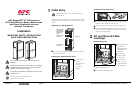
Warnin
g
Always read the separate Safety Sheet 990-2822 prior to the
installation.
Warnin
g
All electrical power and power control wiring must be installed by
a qualified electrician, and must comply with local and national
regulations for maximum power rating.
Warnin
g
The UPS must be supplied from a: 208Y/120V or 220Y/127V 4W+
GND 60 Hz source.
Note
Power terminal lug diameter: minimum 6 mm.
Torque value: 62 lbf
.
in/7 Nm.
1
Cable Entry
Cable entry takes place from the rear of the UPS. Pull out the lower end of
the handle and turn it counterclockwise to a horizontal position to open
the door.
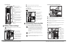
Preparing for cabling (general)
Use a torx screwdriver to loosen the four M4 screws from the cable
landing cover and remove.
Preparing for bottom and top entry
Use a hammer to
punch out
knockouts and line
holes with
grommets (not
supplied).
Note
Make sure that the UPS is in its location of use before you
start the cabling.
Cable landing area
for AC input
Power Distribution
Unit (PDU)
Conduit box
Power module with
cable landings for
battery cables and
communication
cables
Smart-UPS® VT ISX w/transformer and PDU, 20-30 kVA, 480 V, Installation
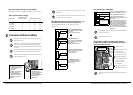
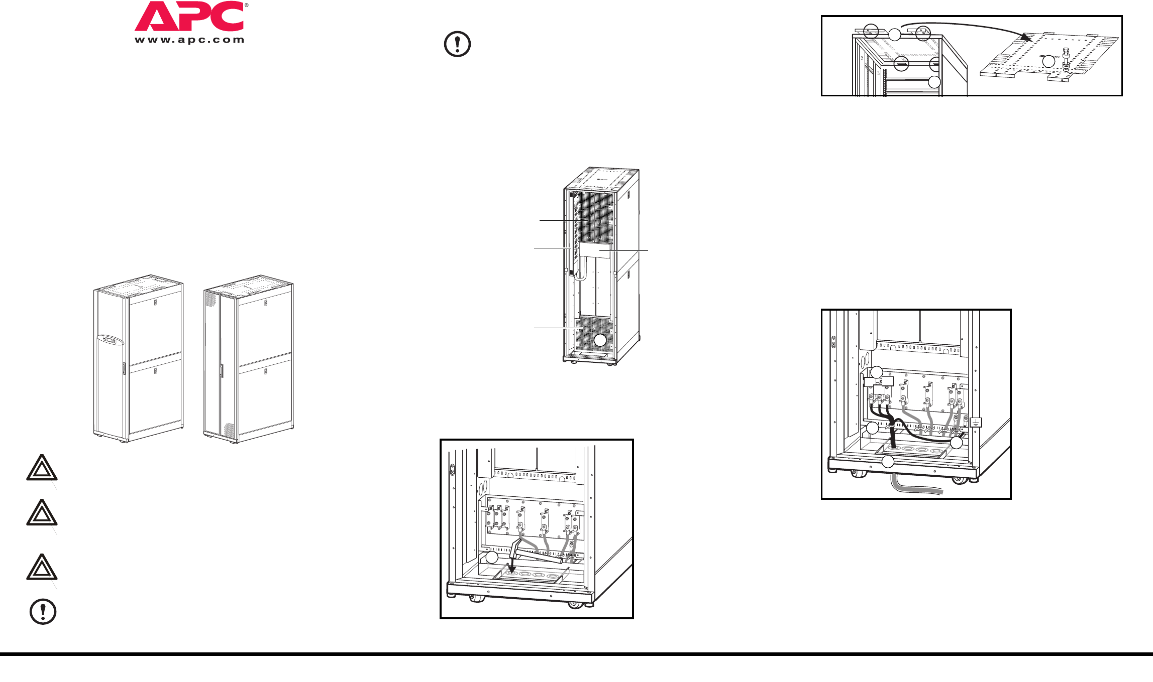
Preparing for top cable entry
From the rear of the inside of the UPS push the top cover spring locks
backwards to lift up the rear end of the top cover.
Slide out the top cover (mind the wing on either side of the plate).
Punch holes in labeled area between the two rails on the rear of the
top cover for conduits as required. Line hole(s) with grommets (not
supplied). Reinstall the top plate.
2
AC and Ground Cable
Landings
Bottom cable entry
Feed the input cables
in conduits (not
supplied) through the
punched holes in the
bottom plate.
Use cable ties to
attach the cables to
the slotted plate.
Connect the input
cables (L1, L2, L3),
to the cable landings.
Connect the ground cable using the provided screw (earth symbol
beneath the applicable screw).
Reinstall bottom cable landing cover.
Rear
L1
L2
L3