


Smart-UPS® VT ISX w/transformer and PDU, 20-30 kVA, 480 V, Installation
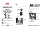
Disconnecting the load from the PDU(s)
To disconnect the load, set the applicable breaker to the OFF position.
PDU output breaker ratings
5
Communication Cables
Rear of unit
Ambient temperature
in front of unit ºC Nominal rating of breaker
20 50 63
Free exhaust 20 17
42.5 53.55
Free exhaust 30 16 40.0 50.40
Free exhaust 40 15 37.5 47.25
Hot aisle exhaust 25 16 40.0 50.40
Note
Emergency Power Off (EPO) switch must be connected to a
NEC Class 2 circuit.
Note
Use only 28-16 AWG copper wire for the connection of the
EPO switch and other optional equipment. Keep all other
wiring and uninsulated live parts separate of other NEC Class
2 circuits.
Note
Do not connect any circuits to the EPO terminal block unless it
can be confirmed that the circuit is a NEC Class 2 circuit.
Note
Remove top cable landing covers as described under Battery
Cable Landings, top entry.
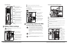
J108 Pin Connections:
1 Normally open EPO
2 Normally open EPO return
3 Normally closed EPO
4 Normally closed EPO return
5 +24V SELV supply
6 SELV ground
J106 Pin Connections:
8 Ext. charging control return
7 External control of charging
6 Q3 active return
5 Q3 active
4 Battery measurement supply*
3 Battery unit quantity*
2 Max. battery temperature*
1 Battery measurement return*
* Should be used with APC XR
Enclosures
EPO (Emergency Power Off) switch wiring – pin
connections J108 (for EPO wiring options)
Connect the EPO cable, using one of the following 4 wiring
configurations:
Note
The UPS must be connected to either a dry contact or a 24 V
DC
EPO switch.
Note
Always follow the pin connection procedures from the top and
work down: J106 (8-1), J108 (1-6).
1
2
3
4
5
6
J108
1: Dry Contracts Normally Open
EPO circuit
EPO is activated when pin 1 is connected
to pins 3 and 5.
Prewired connection 2-4-6, 3-5 and
1 =>
EPO circuit
1
2
3
4
5
6
J108
2: +24V Normally Open
EPO is activated when an isolated SELV
24V
DC
voltage is supplied on pin 1 with
reference to pin 2.
Prewired connection 3-5 and 4-6
1
2
3
4
5
6
J108
3: Dry Contacts Normally Closed
EPO circuit
EPO is activated when a connection from
pin 3 to pin 5 is opened.
Prewired connection 4-6.
1
2
3
4
5
6
J108
4: +24V Normally Closed
EPO circuit
EPO is activated when a SELV 24V
DC
voltage removed from pin 3 with
reference to pin 4.
Smart-UPS® VT ISX w/transformer and PDU, 20-30 kVA, 480 V, Installation
Pin connections J106 (UPS)
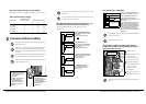
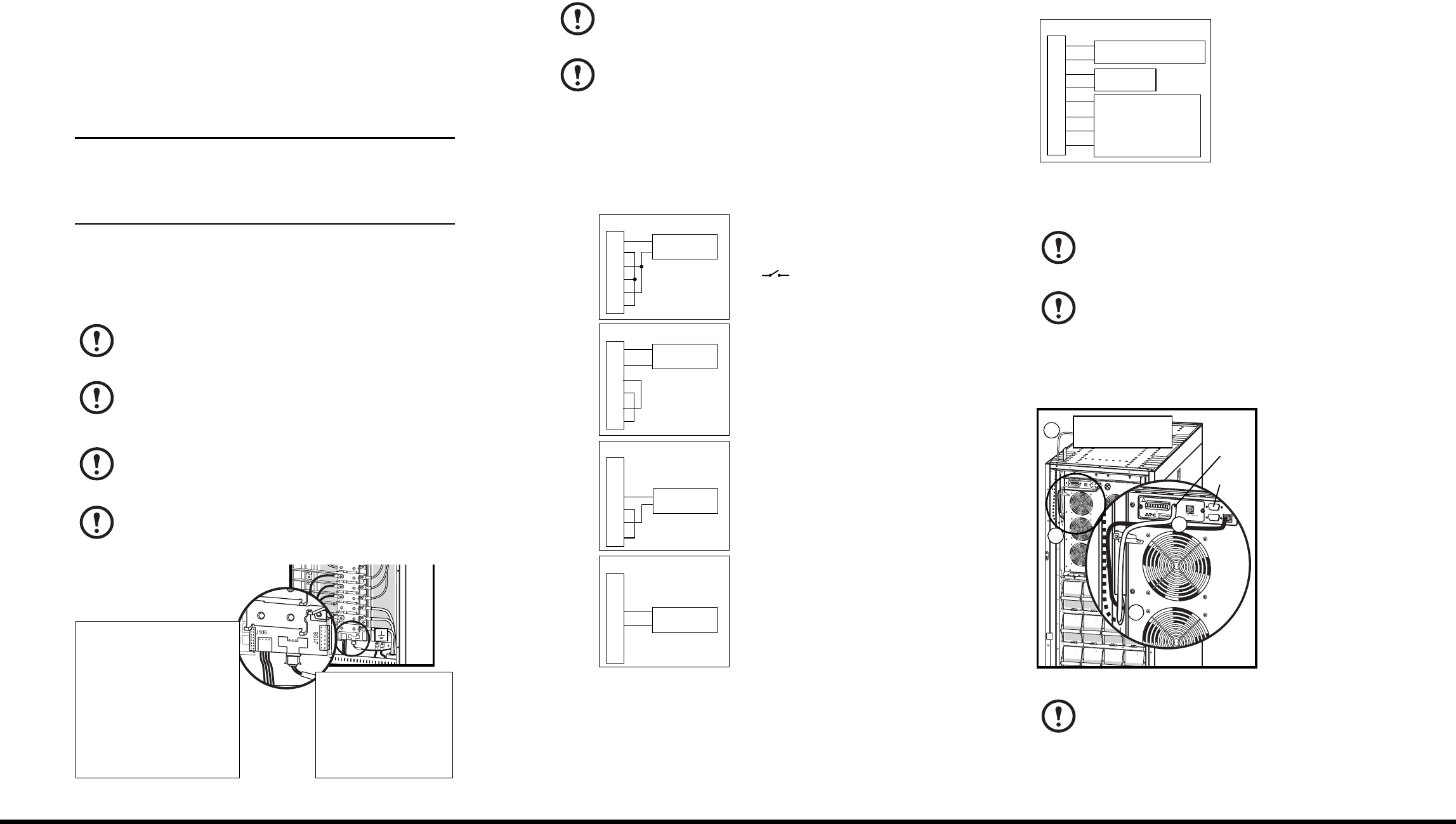
Connection of APC communication options –
PowerChute software and temperature sensor
(identical cable routing)
Open front door.
Feed cables from optional
communication
equipment through the
opening in the top cover.
Guide the cables along
the inside of the left side
panel down to the
opening in the power
module frame.
Connect communication
equipment where shown.
Note
When connecting the Q3 auxiliary signal, use gold-plated N/C
auxiliary switch on Q3.
Note
Reinstall cable landing covers.
Note
The APC communication options are provided at the front of
the UPS.
8
7
6
5
4
3
2
1
J106
Q3 switch
Charging control switch
J200 (XR Batteries)
4
3
2
1
Pins 1 to 4 are for battery measurement (only
applicable to APC XR Battery Enclosures).
Pins 5 and 6 are for external maintenance
bypass Q3 (auxiliary switch N/C type).
When Q3 is closed, signals are fed back to the
UPS controller.
Pins 7 and 8 are for external charge control.
When 7 and 8 are closed, the UPS charges
batteries with a pre-defined percentage (0-25-
50-75-100%) of the maximum charging power.
To be used in generator applications, or if
special codes requires control of charging.
When Q3 is closed, signals are fed back to the
UPS controller.
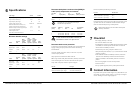
10/100Base
-T
Probe
A
P9619 N
etwork Mana
gement Card EM
!
Reset
Output
P
wr
Zone
1
0/100
M
o
d
e
l:
Ser
i
al:
BA
TTERY UNIT
Model:
S
eri
a
l
:
BATTERY UNIT
Model:
S
e
r
ia
l
:
BATT
ERY UNIT
Mo
d
e
l:
Se
r
ia
l
:
BATTE
RY UNIT
Mo
d
e
l
:
Seria
l:
BATTERY UNIT
M
o
d
e
l:
Se
r
ial
:
BATTERY UNIT
Model:
S
e
ri
al:
BATTERY UNIT
Mod
e
l
:
S
e
r
i
al:
BATTERY UNIT
M
od
el
:
S
e
ri
a
l:
BATTERY UNIT
Mod
e
l
:
Ser
ial:
BATTERY UNIT
Mode
l
:
S
eria
l
:
BATTERY UNIT
Mo
d
el
:
S
er
ia
l
:
BATTERY UNIT
10/100Base-T
Probe
AP9619 Network Management Card EM
!
Reset
Output
Pwr
Zone
10/100
Temperature sensor/
PowerChute software
Temp.
sensor
Power
Chute