


Page 20
6.0 UPS monitoring
6.4 Computer interface port
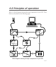
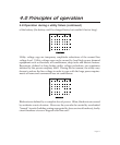
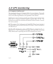
The computer interface port is diagramed below for your reference. Those with
technical abilities wishing to use this port in a special application should be
aware of the following limitations and capabilities of the interface.
6.4.1 Outputs at pins 3, 5 and 6 are actually open collector outputs which must be
pulled up to a common referenced supply no greater than +40 Vdc. The
transistors are capable of a maximum non-inductive load of 25 mAdc. Use only
Pin 4 as the common.
6.4.2 The output at Pin 2 will generate a LO to HI RS-232 level upon transfer of
the output load to power derived from the UPS’s battery. The pin is normally at
a LO RS-232 level.
6.4.3 The UPS will shut down when a HI RS-232 level, sustained for 0.5 s, is
applied to Pin 1. The UPS responds to this signal, following a delay, only during
utility failures (load is operating from the UPS’s internal power source).