


Copyright © 2002 American Power Conversion Corporation
Battery Replacement Troubleshooting
Battery replacement is a safe procedure, isolated from electrical hazards.
Do not replace the battery when the UPS is On-Battery.
Please refer to the diagrams in the “Connect Battery” section during this procedure.
Procedure:
1. Switch “Off” and unplug all equipment from the UPS.
2. Switch “Off” the UPS and unplug it from the wall outlet.
3. Refer to the Step 1 in the “Connect Battery” section of the manual for instructions on how to open the
battery compartment.
4. Disconnect the battery wires one at a time; grasp each wire connector and pull straight back. Take care not
to pull the wires.
5. Remove the old battery.
Note: Small sparks at the battery connections are normal during connection.
6. Connect the red wire to the positive (+) battery terminal of the replacement battery. Connect the black wire
to the negative (-) battery terminal.
7. Tip the new battery, terminal side first, into the battery compartment. Press the battery gently until the
retaining clip snaps into place.
8. Slide the battery compartment cover back into place. The UPS needs to be connected to utility power for at
least 4 hours before full runtime can be expected.
Note: The spent battery must be recycled. Deliver the battery to an appropriate recycling facility
or return it (in the new battery’s packing material) to APC. See the new battery instructions
for additional recycling information.
Before storing, charge the UPS for at least 12 hours. Store the UPS covered and upright in a cool, dry location.
Refer to the table below for charging and storage information. Please contact APC Technical Support to
troubleshoot a faulty unit before returning it to APC.
Storage Temperature Recharge Frequency
5 to 86
o
F (-15 to 30
o
C)
86 to 113
o
F (30 to 45
o
C)
Every 6 months
Every month
Charging Duration
12 hours
12 hours
Specifications
Acceptable Input Voltage
Input Voltage (on line)
Output Voltage
Frequency Limits (on line)
Max. Load - Battery Power Supplied Outlets
Max. Load - Surge Protected Only Outlets
Maximum Branch Circuit Overcurrent Protection
Requirement
Operating / Storage Temperature
Operating and Storage Relative Humidity
Operating Elevation / Storage Elevation
UPS Size (H x W x D) excluding power cord
UPS Weight
Shipping Weight
EMI Classification
0-150 Vac, Single Phase
98-139 Vac
106-124 Vac
47 - 63 Hz
500 VA, 325 W
10 A
20 A
Caution: To reduce the risk of fire, connect only
32 to 104
o
F (0 to 40
o
C) / 5 to 113
o
F (-15 to 45
o
C)
0 to 95%, non-condensing
0 - +10,000 ft. (0 - 3,000 m) /
2.7 in. x 17.0 in. x 7.0 in.
9.1 lb. (4.2 kg)
FCC/DOC Class B
to a circuit provided with 20 amp maximum branch
circuit overcurrent protection in accordance with
National Electrical Code ANSI/NFPA.
0 - +50,000 ft (0 - +15,000 m)
8.6 lb. (3.9 kg)
17 Minutes
On-Battery Runtime - Typical
Desktop Computer and 15" Monitor (110 watts)
Warranty
The standard warranty is 2 years from the date of purchase. APC’s standard procedure is to replace the
original unit with a factory reconditioned unit. Customers who must have the original unit back due to
assigned asset tags and set depreciation schedules must declare such a need at first contact with APC
Technical Support. APC will ship the replacement unit once the defective unit is received by the repair
department or cross-ship upon the provision of a valid credit card number. The customer pays for shipping to
APC, and APC pays ground freight transportation costs back to the customer.
Wall Mount of UPS
The UPS can be mounted vertically or horizontally to a wall surface. Use the template below to position the
securing fasteners (not supplied).
Note: Position the On/Off switch to the right for horizontal mounting, and to the top for vertical mounting.
1. Hold this page against the wall in the desired mounting location.
2. Use thumbtacks or tape to hold this page in place. Make sure the template circles line up where the
mounting fasteners are to be installed. Use a sharp nail or pin to puncture the center of each appropriate
template circle to mark the wall.
3. Install fasteners at the marked locations. Leave the head of both fasteners 5/16” (8 mm) out from the
surface of the wall. Fasteners must be able to support 15 lb (6.8 kg).
4. Mount the UPS by positioning the key-hole slots over the fastener heads. For vertical mounting, slide the
unit down into place. For horizontal mounting, turn it slightly counterclockwise until it is securly in place.
Horizontal and Vertical
Mounting
Vertical Mounting Only
Horizontal Mounting Only
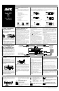
Solution
Replace Battery indicator
Symptom Possible Cause
The battery wire is Connect the battery wire as shown in Step 1 of
is lit. not connected. the
Installation
section (front page).
Battery has reduced
Unplug one (or more) device
capacity due to frequent
from the UPS and reset the
or long outages, or needs
to be replaced.
circuit breaker by pressing
it fully inward.
Circuit breaker popped The outlets are severely
up (tripped). overloaded.
Charge the UPS overnight. Then, switch the UPS
Off and then On. If the Replace Battery indicator
is still lit, the battery needs to be replaced. If the
UPS is under warranty, contact APC Technical
Support. If the UPS is not under warranty, see
Order Replacement Battery
on the front page.
The UPS battery becomes discharged during power
outages. Keep the battery charging (by keeping the
UPS plugged into utility power) for up to 20 hours
after a power outage. Recharge may occur in less
UPS does not provide The battery is not fully
expected runtime. charged, or is depleted by
frequent power outages.
time - depending on the battery capacity.
Consider the purchase of a replacement battery.The battery is near the
end of its useful life.
1. Perform a Manual Shutdown (see front page).
2. Switch the UPS Off.
3. Unplug one device from the Battery Power
Supplied outlets.
Flashing On Battery The Battery Power
indicator and constant Supplied outlets are
overloaded.
4. Switch the UPS On.
tone.
If the overload indication disappears, the problem
is solved. Repeat the procedure if the overload
condition persists.
Switch the UPS Off and then On. If the sameFlashing Replace Battery A UPS internal battery
indicator and continuous
tone.
charger fault has occurred. symptoms appear, disconnect the UPS from
utility power to prevent possible battery damage
and contact APC Technical Support.
Please, Do Not Return the Unit to the Place of Purchase Under any Circumstances!
1. Consult the Troubleshooting section to eliminate common problems.
2. Verify the battery is connected as shown in the Battery Replacement section on this page and that the circuit
breaker is not tripped (see Troubleshooting section).
If you still have problems or questions, please contact APC via the Internet or at one of the phone numbers
listed at the bottom of the page.
3. Before contacting APC, please be sure to record the date purchased, UPS model, and serial number (on bot-
tom of UPS).
4. Be prepared to troubleshoot the problem over the telephone with a Technical Support Representative. If this
is not successful, the Technical Support Representative will issue a Return Merchandise Authorization Num-
ber (RMA#) and a shipping address.
5. Pack the UPS in its original packaging. If the original packing is not available, ask APC Technical Support
about obtaining a new set. Pack the UPS properly to avoid damage in transit.
Never use Styrofoam™ beads for packaging. Damage sustained in transit is not covered under warranty
(insuring the package for full value is recommended).
6. Write the RMA# on the outside of the package.
7. Return the UPS by insured, prepaid carrier to the address given to you by APC Technical Support.
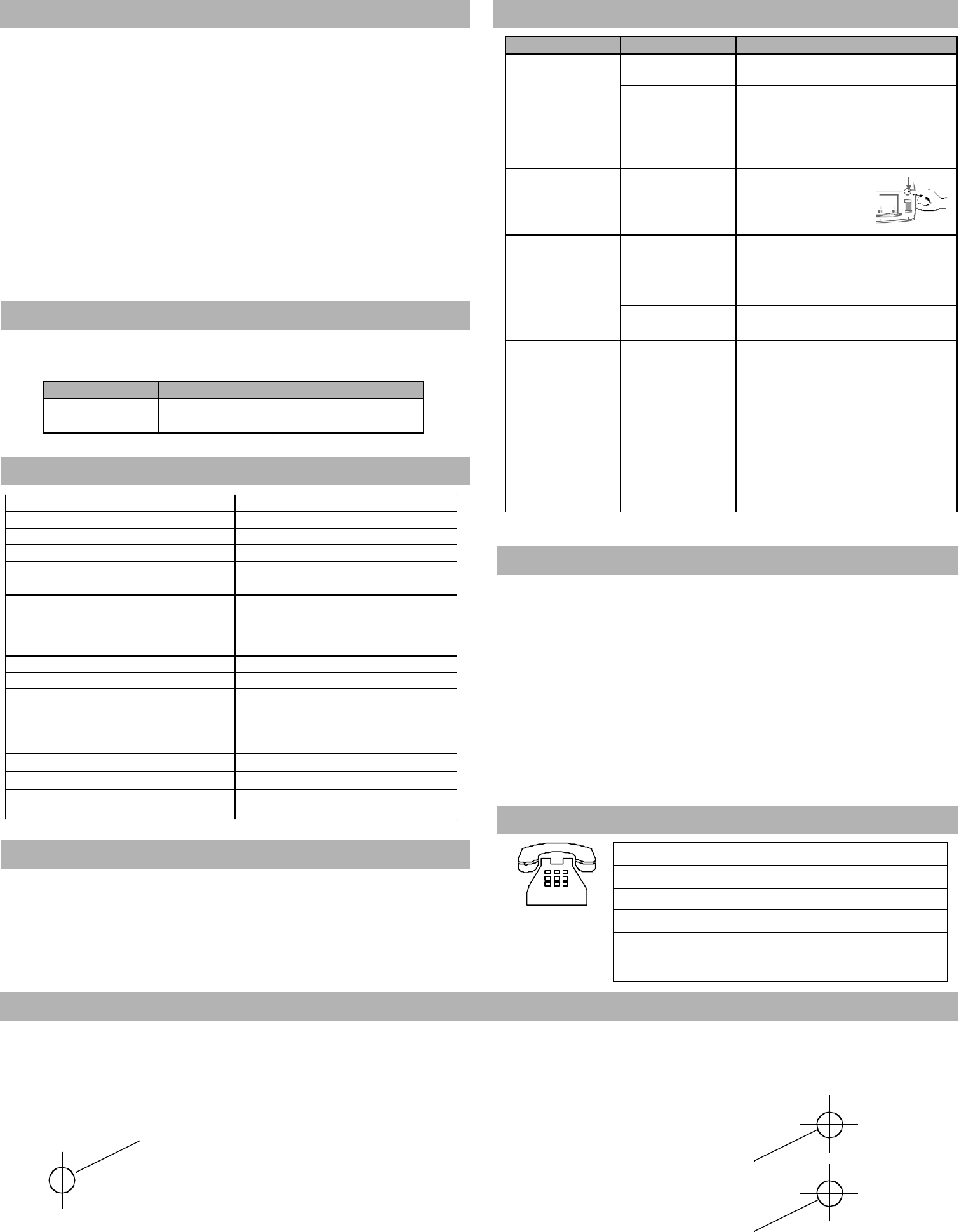
Service
USA/Canada
Mexico
Brazil
Worldwide
Internet
Technical Support
1.800.800.4272
292.0253 / 292.0255
0800.12.72.1
1.401.789.5735
http://www.apc.com
http://www.apc.com/support
APC Contact Information
Storage