


38 AIS® 3000 10-40kVA, 400V, Site Preparation and Installation Manual – 990-2258
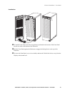
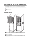
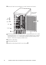
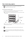
Remove the 2 M6x12 screws from Brackets A, B, and C and remove all 3 brackets.
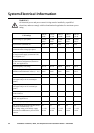
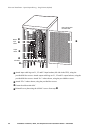
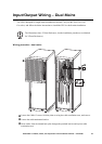
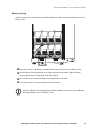
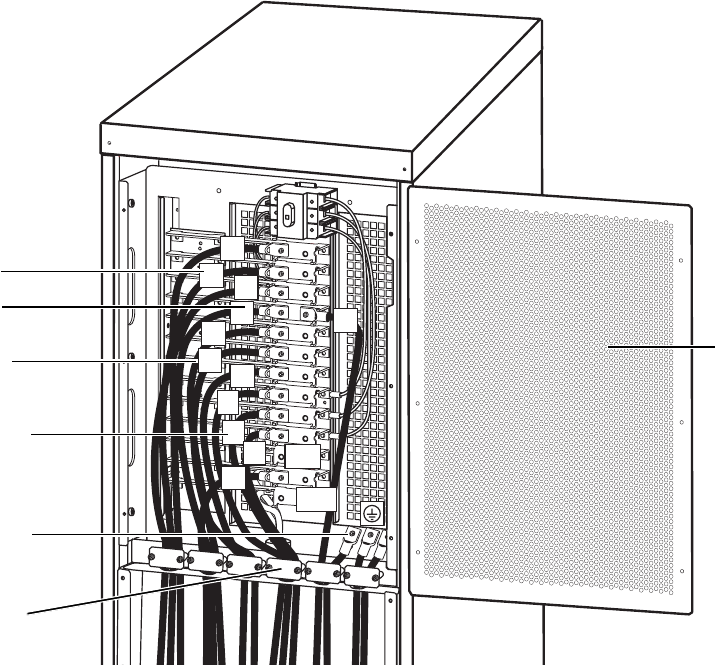
Attach the input cable lugs to input busbars L1, L2, L3, using the provided hex screws. Attach
the bypass cable lugs to L1, L2, L3 bypass busbars, using the provided hex screws. Attach the
output cable lugs to the L1, L2, L3 output busbars and attach, using the provided hex screws.
Attach N x 3 where shown, using the provided hex screws.
Attach PE x 3 where shown.
Fasten the cable strain relief.
Reinstall cover plate using the 6 M4x13 screws from step .
N
N
Batt
+
L
1
L
3
L
2
Batt–
N
L
1
L
3
L
2
L
3
L
2
L
1
PE cables
Neutral
Input
Bypass
Output
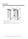
Plate covering cable
termination area