


Appendix
990-4056
Installation Guide APC Silcon 240-320kW 400V UPS 71
9.0 Appendix
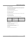
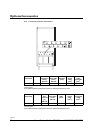
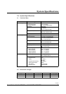
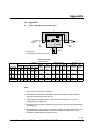
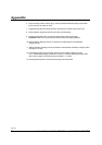
9.1 Table 1. Installation Planning Data
Notes:
1. Nominal input current based on rated load.
2. Maximum input current based on rated load + full battery recharge. Full battery recharge
assumed to increase input current with 10%.
3. Nominal power consumption (column 1c) based on nominal input current (1e) and the
corresponding input voltage (1a).
4. Maximum power consumption (1d) based on maximum input current (1f) and the corresponding
input voltage (1a).
5. Suggested input overcurrent protection (1h) based on continous full load maximum input current
(1f). MCCB breaker selection based on continous full load nominal input current (1e) is
acceptable, provided battery recharge time is short.
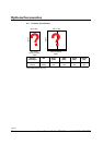
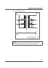
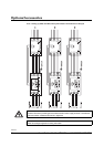
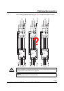
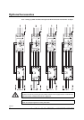
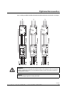
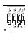
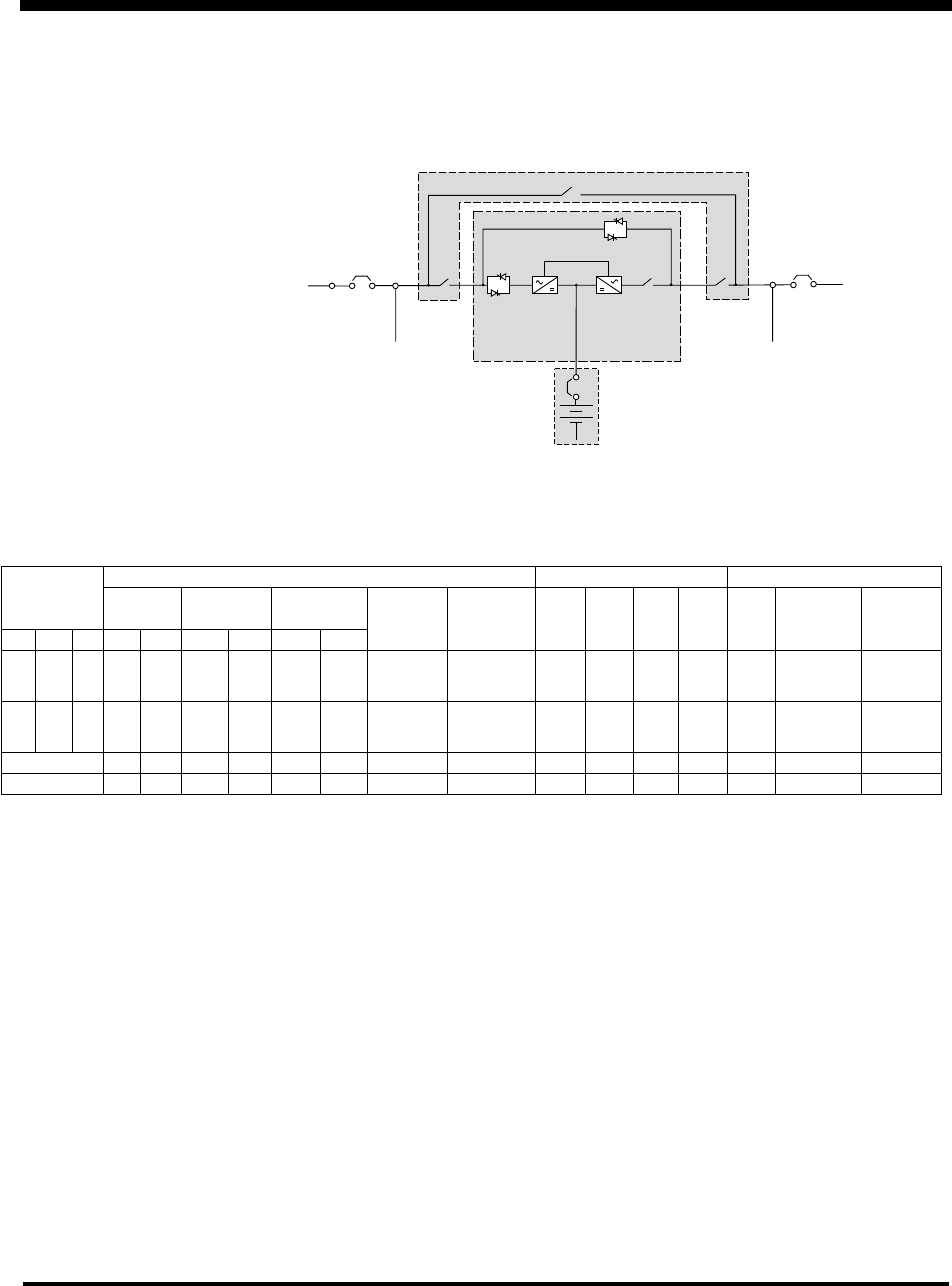
Main Input
Breaker
Field
Wiring*
Battery Bank**
UPS Module
Service Bypass Panel
Field
Wiring
Output
Breaker
*
** Internal Batteries available for 40kW units and smaller
*
*
Q1
Q2
Q3
* Not supplied by APC
Installation Planning Data
APC Silcon Series
AC Input Battery System DC AC Output
Min. Input Input Full I
Nom
I
Max
Load side Heat
Power rating Source P (kW) I (A) Cable Overcurrent V
n
load Disch Disch I
n
Overcurrent Dissipation
kW kVA Pf V Hz Nom. Max. Nom. Max. (per phase) Protection* (Vdc) P(kW) (A) (A) (A) Protection* (kW)
240 240 1 380
400
415
50/60 256.6 307.5 421.7
403.5
386.6
463.9
443.8
425.3
2//125mm
2
500 A 2x384 252.7 329 388 363.6
347.8
333.3
400 A 9.2
320 320 1 380
400
415
50/60 333.9 407.4 558.8
507.3
512.3
614.7
588.0
563.5
2//200mm
2
630 A 2x384 334.8 436 514 484.8
463.8
444.4
500 A 10.6
COLUMN 1a 1b 1c 1d 1e 1f 1g 1h 2a 2b 2c 2d 3a 3b 4a
NOTES 3 4 1 2 9 5, 6, 13 8 12 10 11 6, 7 13
* Provided by others