


Equipment Performance
For planning purposes, in order to obtain maximum system performance, the SPD must be located as close to the
circuit to be protected as possible, minimizing the interconnecting wire length. For every foot of wire length,
approximately one (1) nanosecond of turn-on/turn-off time is added, and approximately 175 volts (6kV/3kA, 8/20
microseconds) is added to the clamp voltage.
For optimum transient surge protection, staged surge suppression should be implemented at the service entrance and
all other electrical connections to the building (telephone, CATV, etc.). It should also be implemented at recognized
surge generating loads within the building (arc welding rigs, large motors, switched capacitors, etc.). Additionally, it
should be implemented for sensitive electronic loads (computer equipment, facsimile machines, copy machines, solid
state motor drives, variable frequency drives, etc.). For interconnected electronic loads (via data cabling), surge
protection devices should also be utilized to protect the devices on either end of the interconnecting data cables.
APC manufactures a complete line of surge protection devices for both alternating current (AC) and direct current
(DC) applications. Contact an authorized APC reseller, or order directly from APC at www.apc.com.
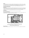
Product Orientation
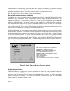
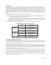
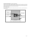
To decode the Model Number and determine the unit’s configuration, locate the printed nameplate on the outside of
the unit. Note: The Serial Number, Date of Manufacture, and Suppression Voltage Rating (SVR) are also on the unit
identification nameplate. The Model Number can be decoded as follows:
• PM identifies a SurgeArrest Panel Mount product. The following letter indicates the voltage and wiring
configuration of the device.
• Following this letter is the number 3. This number identifies the surge current ratings to be 120kA per phase.
• Following the number 3 is the letter X. This indicates that the unit is non-modular.
• Following the "X" letter designation are the letters LM, which indicates that this model has been designed
for use in South America.
Options are detailed later in this manual.
System Grounding
For planning purposes, equipment grounding conductor must be used on all electrical circuits connected to the SPD.
This requirement is primarily for safety, although SPD performance is enhanced by proper grounding. Proper
operation of any surge suppression system or device depends on a proper grounding system. Incorrect grounding
practices will reduce the effectiveness or interfere with SPD system operation and performance, as well as endanger
personnel and equipment. For the best performance, use a single point ground system where the service entrance
grounding electrode system is connected to and bonded to all other available electrodes, building steel, metal water
pipes, driven rods, etc. For sensitive electronics and computer systems, the recommended ground impedance
measurement is 25 ohms or less. When a metallic raceway is used as an additional grounding conductor, an insulated
grounding conductor should be run inside the raceway. Adequate electrical continuity must be maintained at all
raceway connections. Do not use isolating bushings to interrupt a metallic raceway run. A separate isolated ground
for the SPD is NOT recommended.
Page 3
• INSTALLATION or MAINTENANCE OF THIS SURGE PROTECTION DEVICE MUST BE
PERFORMED BY QUALIFIED PERSONNEL ONLY.
• DURING NORMAL OPERATION, HAZARDOUS VOLTAGES ARE PRESENT INSIDE THE UNIT.
• WHEN SERVICING THIS UNIT, SERVICE PERSONNEL MUST BE SURE TO FOLLOW ALL
ELECTRICAL SAFETY PRECAUTIONS.
• ALL POWER SOURCES TO THIS UNIT SHOULD BE LOCKED OFF BEFORE SERVICING.
THIS WILL PREVENT THE RISK OF RECEIVING AN ELECTRICAL SHOCK.
WARNING