


9
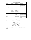
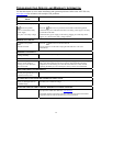
NOTE: SETTINGS ARE MADE THROUGH SUPPLIED POWERCHUTE SOFTWARE OPTIONAL SMART SLOT
ACCESSORY CARDS OR TERMINAL MODE.
FUNCTION
F
ACTORY
DEFAULT
USER SELECTABLE
CHOICES
D
ESCRIPTION
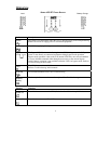
Low Bypass Point -30% of output
voltage setting
-15%, -20%, -25%, -30% Minimum voltage that the UPS
will pass to connected
equipment during internal
bypass operation.
Output Voltage XLJ models:
200 VAC
XLT models:
208 VAC
XLI models:
230 VAC
XLTW models:
220 V
XLJ models:
200 VAC
XLT models:
200, 208, 220, 230,
240 VAC
XLI models:
200, 208, 220, 230,
240 VAC
XLT/XLTW models:
200, 208, 220, 230,
240 VAC
Allows the user to select the
UPS output voltage while
online.
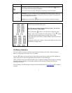
Output Frequency Automatic
50 ± 3 Hz or
60 ± 3 Hz
50 ± 3 Hz
50 ± 0.1 Hz
60 ± 3 Hz
60 ± 0.1 Hz
Sets the allowable UPS output
frequency. Whenever possible,
the output frequency tracks the
input frequency.
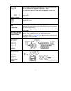
Number of
Battery Packs
1 Number of Connected
Internal Battery Packs,
(two modules per pack)
Defines the number of internal
and external connected battery
packs for proper run time
prediction.
C
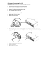
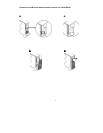
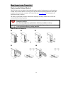
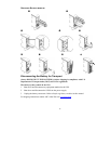
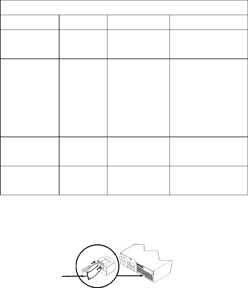
ONNECTING THE EPO (EMERGENCY POWER OFF) OPTION
The output power can be disabled in an emergency by closing a switch connected to the EPO.
Adhere to National and local electrical codes when wiring the EPO.
The EPO switch is internally powered by the UPS for use with non-powered switch circuit breakers.
The EPO circuit is considered a Class 2 circuit, (UL, CSA standards) and a SELV circuit (IEC
standard).
EPO
switch