


CHAPTER 3: INSTALLATION
7
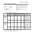
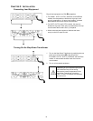
Front View Component Identification
Figure 2: AP9621
Figure 3: SUTF3 / SYTF2 / SYTF2J /
SYTF3 / SYTF3J
Figure 4: SURT005/ SURT006
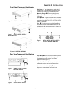
Rear View Component Identification
Figure 5: AP9621 / SYTF2 / SYTF2J /
SURT005 / SURT006
Figure 6: SUTF3 / SYTF3 / SYTF3J
Rail Cleats
: Two cleats (one on each side) of
the Step-Down Transformer engage with the rack
mounting rails to secure in the equipment rack.
Mounting Flanges : Two mounting flanges
(Figure 2 and 4) secure the Step-Down Transformer
in the rack.
Front Bezel
: A bezel covers the front of the Step-
Down Transformer. The bezel is removed during the
installation for the SUTF3, SYTF2, SYTF2J, SYTF3
and SYTF3J models.
Fans
: Two fans on the front of the Step-Down
transformer circulate airflow and cool the unit. The
redundant fan will not operate unless the internal
temperature of the unit becomes 100 °F or failure of
the main cooling fan.
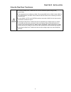
Figure 7: SUTF3 / SYTF2 / SYTF2J / SYTF3 /
SYTF3J / SURT005 / SURT006
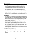
Input Wiring
: Provides access to wiring terminal
blocks for hard wiring the input (see Figure 6).
Provided with an input cord for use in many
applications (see Figure 7).
Input Circuit Breaker
: The input circuit breaker
protects the product and load equipment from
extreme overloads.
Power Distribution Unit (PDU)
: Power
distribution receptacles for connecting load
equipment.