


2–1
Chapter 2
22
2
Product Reference
Overview
This chapter contains the technical information required to install and configure the
Little Board™/486e CPU. The information includes:
! Power Connector
! DRAM memory
! Serial Ports
! Bi-directional parallel port
! Floppy disk interface
! IDE hard disk interface (Compact Flash)
! Video Controller
! 32-pin byte-wide socket
! Ethernet local area network interface
! Utility connector (keyboard, PC speaker, reset button, external battery, PS/2 mouse)
! Watchdog timer
! Battery-backed clock
! PC/104-compatible expansion bus
! SETUP function
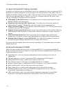
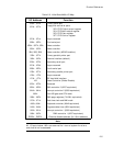
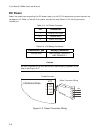
Interface Connector Summary
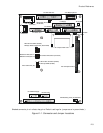
Refer to Figure 2–1 for the locations of the connectors (P1A/B, P2C/D, J2 – J7, J11 – J16) and
configuration jumpers (W1 – W14). Table 2–1 summarizes the use of the I/O connectors and Table
2–2 summarizes use of the configuration jumpers. Each interface is described in its own section,
showing connector pin outs, signal definitions, required mating connectors, and configuration
jumper options.
Many of the connectors have a key pin removed. This allows you to block the corresponding cable
connector socket to help prevent improper assembly and possible board damage. Table 2–1
indicates which pins are key pins, and Figure 2–1 shows their locations.