


Little Board™/486e Technical Manual
2–2
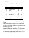
Table 2–1. Connector Usage Summary
Connector Function Size Key Pin
P1A/B PC/104 Expansion Bus 64-Pin B10
P2C/D PC/104 Expansion Bus 40-pin C19
J2 Compact Flash Card 50-pin
J3 Flat Panel Video 50-pin 35
J4 LCD Bias Supply Connector 12-pin 3, 10
J5 CRT Video 10-pin None
J6 RS-485 2-pin None
J7 Ethernet Twisted Pair RJ45 None
J10 Power, +5V and +12V 4-pin
Molex
None
J11 Serial 1 and Serial 2 20-pin 20
J12 IDE Hard Disk 40-pin 20
J13 Serial 3 and Serial 4 20-pin 20
J14 Floppy Interface 34-pin 6
J15 Parallel Port 26-pin 26
J16 Utility/Keyboard 16-pin 2
Connectors
The I/O connectors are dual-row headers for use with insulation displacement connectors (IDC) and
flat ribbon cable.
A number of the connectors have key pins. Install a blocking key in the corresponding connector
socket on the mating ribbon cable to prevent misalignment.
You can design PC boards with female connectors in the same relative positions as the Little
Board’s connectors. This eliminates cables, meets packaging requirements, adds EMI filtering, or
customizes the installation in other ways.
The PC/104-compatible expansion bus is located on connectors P1A/B and P2C/D. The system can
be expanded using Ampro MiniModule expansion products or other PC/104-compliant expansion
modules. These modules can be attached by stacking them directly on the P1 and P2 connectors or
by using standard or custom expansion hardware; including solutions available from Ampro.
Contact your Ampro sales representative for information about alternatives offered by Ampro.
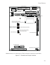
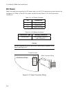
If you plan to use the on-board video controller with a flat-panel LCD that requires a Vee voltage,
you can install Ampro’s optional LCD Bias Supply board on connector J4, as shown in Figure 2-1.
This board can be jumpered to supply positive or negative Vee from ±15V to ±35V (adjustable).