


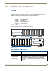

NXF CardFrame and NetModules
4
NetLinx Cardframe, Control Cards, and NetModules - Operation Reference Guide
Mounting modules into an equipment rack
To install the modules in an equipment rack using the optional AC-RK kit:
1. Remove the front faceplate from the module to expose the mounting holes.
2. Mount the module on the AC-RK bracket.
3. Place the AC-RK bracket (with the module) in the equipment rack and secure the bracket to the rack.
4. Replace the front faceplate on the module, and attach the translucent plastic cover to the faceplate (if necessary).
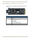
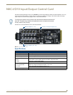
Installing Control Cards into an NXF CardFrame
1.
Remove the magnetic front faceplate/viewing window from the CardFrame.
2. Align the edge of the Control Card with a slot in the CardFrame. Slide the card into the CardFrame and press until
you feel the Card seat in the backplane connector.
3. Put the magnetic faceplate back on the CardFrame. Secure with mounting screws (if necessary).
Preparing/connecting captive wires
1.
Strip 0.25 inch of wire insulation off all wires.
2. Insert each wire into the appropriate opening on the connector according to the wiring diagrams and connector
types described in this section.
3. Tighten the screws to secure the wires in the connector. Do not tighten the screws excessively; doing so may strip
the threads and damage the connector.
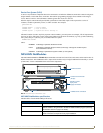
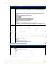
Using the ID button
The ID Button on the rear panel of the NetModules (see FIG. 2) is used in conjunction with the NetLinx Studio software
program to allow you to assign new Device and System numbers for the Module.
1. Using NetLinx Studio, place the system in Identity (ID) Mode. ID Mode means the entire system is put on hold
while it waits for an event from any NetLinx device in the named system (for example, pushing the ID button on a
Module). The device generating the first event is the identified device.
2. Press the ID Mode button to generate an event from the Module and allow you to assign new Device and System
numbers in NetLinx Studio.
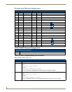
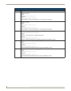
NXS-NMS NetModules Specifications (Cont.)
ICSNet RJ-45 connectors Receives power and data from a NetLinx Master/Hub ICSNet Port.
An ICSNet port on a NetLinx Master or Hub supplies up to 500 mA at 12 V for module
power.
12 VDC power supply connectors Two parallel male 2-pin (green) parallel connectors for 12 VDC power.
Enclosure Metal with black matte finish
Included Accessories NetLinx faceplate
Optional accessories AC-RK Accessory Rack Kit (holds up to three NetModules)