


NXF CardFrame and NetModules
3
NetLinx Cardframe, Control Cards, and NetModules - Operation Reference Guide
Device:Port:System (D:P:S)
A device is any hardware component that can be connected to an AXlink or ICSNet bus. Each device must be assigned a
unique number to locate that device on the bus. The NetLinx programming language allows numbers in the range 0-
32,767. Device 0 refers to the local Master; numbers greater than 32,767 are reserved.
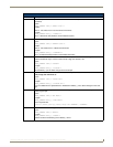
NetLinx requires a Device:Port:System (D:P:S) specification. This D:P:S triplet can be expressed as a series of
constants, variables separated by colons, or a DEV structure. For example:
STRUCTURE DEV
{
INTEGER Number // Device number
INTEGER Port // Port on device
INTEGER System // System the device belongs to
}
The D:P:S notation is used to explicitly represent a device number, port and system. For example, 128:1:0 represents the
first port on device 128 on this system. If the system and Port specifications are omitted, (e.g. 128), system 0 (indicating
this system) and port 1 (the first port) is assumed. Here's the syntax:
NUMBER:PORT:SYSTEM
where:
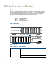
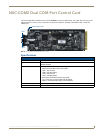
NXS-NMS NetModules
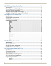
The NXS-NMS NetModules (FG2009-10) accommodate one NetLinx Control Card, and connect to the NetLinx bus via
ICSNet connections. The NetModules offer a simple and economical way to integrate additional functionality to control
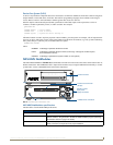
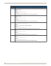
systems. FIG. 2 shows a NetModule shell and its main components.
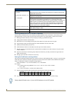
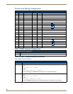
NXS-NMS NetModules specifications
The table below lists the NXS-NMS specifications.
NUMBER: 16-bit integer represents the device number
PORT: 16-bit integer represents the port number (in the range 1 through the number of ports
on the Controller or device)
SYSTEM: 16-bit integer represents the system number (0 = this system)
FIG. 2
NXS-NMS NetLinx NetModule shell
NXS-NMS NetModules Specifications
Dimensions (HWD) 1.50" x 5.55" x 9.25" (3.81 cm x 14.10 cm x 23.50 cm)
ID button Generates an event from the NetModule to allow you to assign new Device and
System numbers, using ID mode in the NetLinx Studio software program (seeUsing
the ID button section on page 4 for details).
Control connector 20-pin black (male) connector that connects the NetModule to external devices.
These connectors are keyed to insure proper installation.
3
NXM-NMS
1720 1819 1516 1314 1012 11 896745
ID
NetModule
12
ICSNet PWR
12VDC
NetModule
ID Button
Parallel 12 VDC
2-pin power
supply connectors
Control Card slot
Control Card connector
ICSNet RJ-45 connectors
(20-pin)
front
rear