


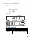

NXF CardFrame and NetModules
2
NetLinx Cardframe, Control Cards, and NetModules - Operation Reference Guide
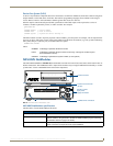
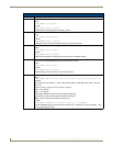
Mounting Master/Hub Cards in an NXF CardFrame
NetLinx Master and Hub Cards can be installed in the NXF CardFrame. The card mounts in a horizontal position,
through the master card slot on the rear panel of the NXF enclosure. To install a Master or Hub Card in an NXF:
1. Discharge the static electricity from your body by touching a grounded metal object.
2. Unplug all the connectors from the NXF.
3. Remove the two screws holding the front plate on the Master Card, and remove the front plate.
4. Align the edges of the card with the guide slots inside the Master Card slot on the NXF.
5. Slide the card about halfway into the slot.
6. Inside the Master Card slot on the NXF, locate the 6-pin control cable connector.
7. Plug the connector from the NXF into the 6-pin terminal on the Master Card. This connector is keyed to ensure
correct orientation.
8. Once the control cable is connected, gently slide the card all the way in until you feel the rear edge of the card
lightly snap into place.
9. Re-apply power and other connections as necessary.
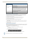
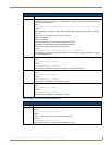
Setting the CardFrame's starting address
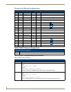
The 8-position CardFrame Number DIP switch, located on the rear of the CardFrame (FIG. 1 on page 1), sets the starting
address (the device number in the D:P:S specification) for the Control Cards installed in the CardFrame. The address
range is 12-3060. The formula for setting the starting address is:
(DIP switch address x 12) + Card slot Number (1-12) = Card address
For example:
For DIP switch setting, 00010101: (0 + 0 + 0 + 0 + 96 + 0 + 384 + 1536) + SLOT #
(ex:1) = 2017.
A card in slot number 7 would be device address 2023.
1. Set the CardFrame Number DIP switch based on the information listed in the table below.
2. Cycle power for approximately 5 seconds, so the system can read the new device number settings.
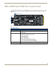
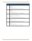
NXF Cardframe Specifications (Cont.)
Rear Panel Components:
Card slots Twelve 20-pin black (male) connectors and mating 3.5 mm captive-screw terminals
supplied with Control Cards.
Control Card connectors (1-12) 20-pin black (male) connectors that connect the Control Cards and external
equipment to the CardFrame.
+12 VDC PWR 2-pin green (male) connector for connecting a 12 VDC power supply. The CardFrame
can be powered via the Master Card (default) or by an external power supply
connected to the CardFrame's PWR connector. If a power supply is connected to the
PWR connector, the CardFrame power automatically switches to the connected
power supply. In that case, the Control Cards and CardFrame are independently
powered. A simple rule to follow is that if the CardFrame contains eight or more
Control Cards, use two 12 VDC power supplies.
CardFrame Number DIP switch Sets the starting address for the Control Cards in the CardFrame. The 8-position DIP
switch address range is 1-3072.
Front faceplate Plastic gray faceplate with translucent viewing window.
Enclosure Metal with black matte finish.
Position 12345678
Value 12 24 48 96 192 384 768 1536
Factory default DIP switch value = 0 (zero) (All DIP switches are in the OFF position).