


Connections and Wiring
6
NXI NetLinx Integrated Controller
IR/Serial Connections and Wiring
You can connect up to eight IR- or serial-controllable devices to the IR/Serial connectors (ports
8-15). These connectors accept an IR emitter (CC-NIRC) that mounts on the device's IR window, or a mini-
plug (CC-NSER) that connects to the device's control jack. The IR/Serial connector wiring specifications are
listed in the following table.
Input/Output (I/O) Connections and Wiring
The I/O port responds to switch closures or voltage level (high/low) changes, or can be used for logic-level
outputs.
You can connect up to eight devices to the I/O connectors (port 16). A contact closure between GND and an I/
O port is detected as a Push. When used for voltage inputs, the I/O port detects a low (0-1.5 VDC) as a Push,
and a high (3.5-5 VDC) signal as a Release. When used for outputs, the I/O port acts as a switch to GND and
is rated at 200 mA @ 12 VDC.
The PWR pin (+12VDC @ 200 mA) is designed as a power output for the PCS2 or VSS2 (or equivalent). The
GND connector is a common ground and is shared by all I/O ports. The following table lists the wiring
specifications for the I/O connectors.
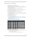
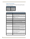
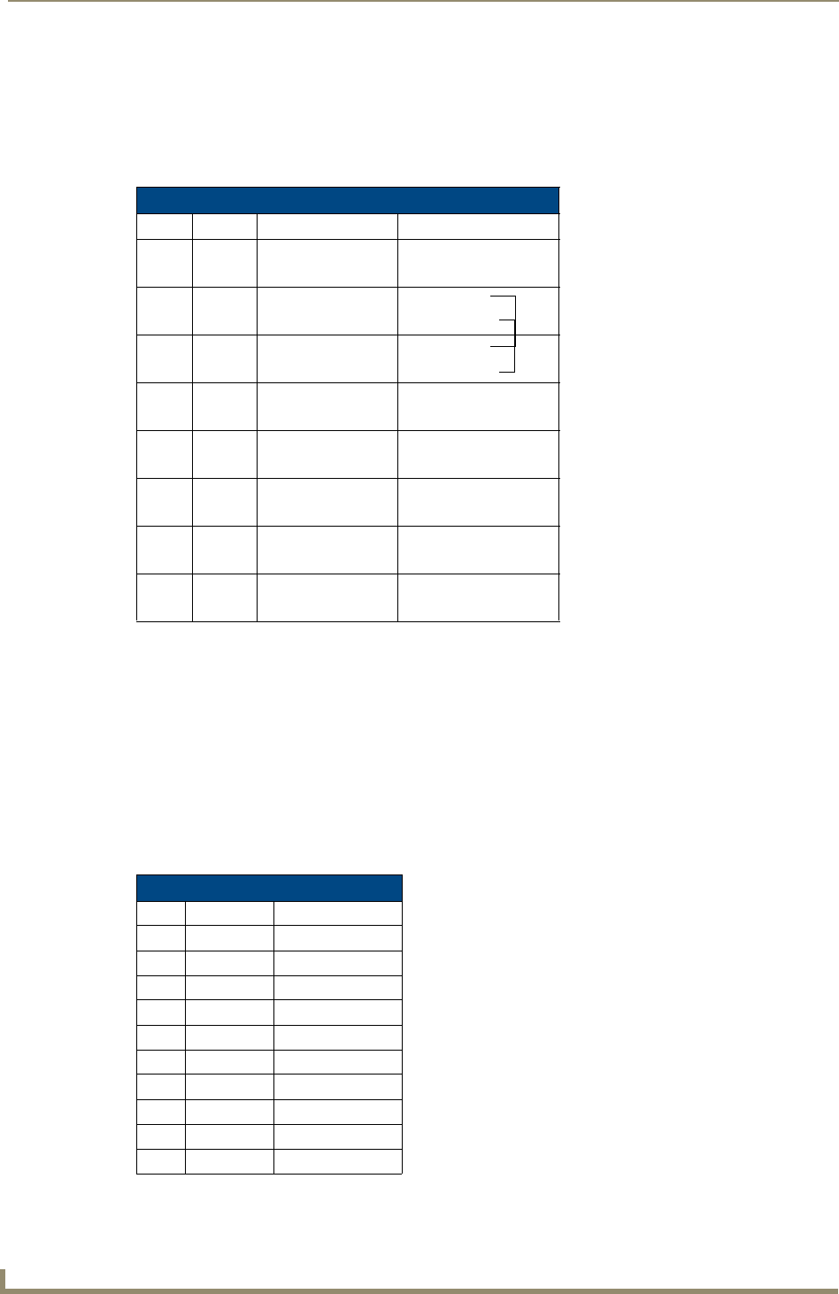
IR/Serial Connector Wiring Specifications
No. Port Signal Function
1 8 GND (-)
Signal 1 (+)
Signal GND
IR/Serial data
2 9 GND (-)
Signal 2 (+)
Signal GND
IR/Serial data
3 10 GND (-)
Signal 3 (+)
Signal GND
IR/Serial data
4 11 GND (-)
Signal 4 (+)
Signal GND
IR/Serial data
5 12 GND (-)
Signal 5 (+)
Signal GND
IR/Serial data
6 13 GND (-)
Signal 6 (+)
Signal GND
IR/Serial data
7 14 GND (-)
Signal 7 (+)
Signal GND
IR/Serial data
8 15 GND (-)
Signal 8 (+)
Signal GND
IR/Serial data
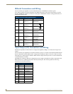
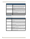
I/O Port Wiring Specifications
Pin Signal Function
1 GND Signal GND
2 I/O 1 Input/output
3 I/O 2 Input/output
4 I/O 3 Input/output
5 I/O 4 Input/output
6 I/O 5 Input/output
7 I/O 6 Input/output
8 I/O 7 Input/output
9 I/O 8 Input/output
10 12 VDC PWR