


Product Information
2
NXI NetLinx Integrated Controller
Specifications
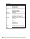
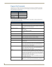
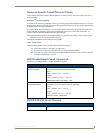
NXI Specifications
Power requirements 1.09 A @ 12 VDC (NXI only/no card)
Memory 64K of IR memory:·
• 32K IR memory for IR ports 8-11
• 32K IR memory for IR ports 12-15
Ports:
RS-232/422/485 ports (#1-6) Six RS-232/422/485 control ports with XON/XOFF (transmit on/transmit off),
and CTS/RTS (clear to send/ready to send), 300-230,400 baud.
Channel range = 1-255
• Channels 1-254 provide feedback only.
• Channel 255 (CTS Push channel): Reflects the state of the CTS Input if a
'CTSPSH' command was sent to the port.
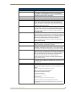
Relay port (#7) 12-channel relay port.
Channel range = 1-12
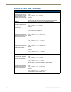
IR/Serial ports (#8-15) 8 IR/Serial control ports that support high-frequency carriers up to 1.14 MHz.
Channel range = 1-32,767
• Channels 1-253 (output): IR commands.
• Channel 254 (feedback): Power Fail (used with 'PON' and 'POF'
commands).
• Channel 255 (feedback): Power status (when IOLink is set).
I/O port (#16) 8-channel I/O port for contact closure, 0-5 VDC voltage sensing, or interac-
tive power sensing for IR ports.
Channel range = 1-8
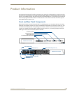
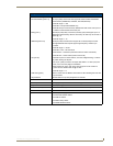
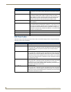
Front panel components:
Card slot Accepts NXC-ME260 NetLinx Master or Hub card.
Hub Cards:
• NXC-NH - Hub Card
• NXC-HS - Hub Server Card
• NXC-HE - Hub Expander Card
RS-232/422/485 LEDs 6 sets of red and yellow LEDs light to indicate ports 1-6 are transmitting or
receiving RS-232, 422, or 485 data:
• TX LEDs (red) blink when transmitting data.·
• RX LEDs (yellow) blink when receiving data.
Relay LEDs 12 red LEDs light to indicate relay channels 1-12 are active (closed).
IR/Serial LEDs 8 red LEDs light to indicate IR/Serial channels 1-8 are transmitting control
data.
I/O LEDs 8 yellow LEDs light when I/O channels 1-8 are active.