


Connections and Wiring
5
NXI NetLinx Integrated Controller
Connections and Wiring
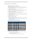
Installing the Master or Hub Card
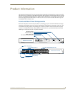
The NXC-ME260 NetLinx Master or any Hub Card can be installed in the NXI. The card mounts in a
horizontal position, through the master card slot on the rear panel of the NXI enclosure (see FIG. 1 on page 1).
To install a Master or Hub Card in an NXI:
1. Discharge the static electricity from your body by touching a grounded metal object.
2. Unplug all the connectors from the NXI.
3. Remove the two screws that hold the front plate on the Master or Hub Card, and remove the front plate.
4. Align the edges of the card with the guide slots inside the Master Card slot on the NXI.
5. Slide the card about halfway into the slot.
6. Inside the Master Card slot on NXI, locate the 6-pin control cable connector.
7. Plug the connector from the NXI into the 6-pin terminal on the Master or Hub Card. This connector is
keyed to ensure correct orientation.
8. Once the control cable is connected, gently slide the card all the way in until you feel the rear edge of the
card lightly snap into place.
9. Re-apply power and other connections as necessary.
Preparing/connecting captive wires
1.
Strip 0.25 inch of wire insulation off all wires.
2. Insert each wire into the appropriate opening on the connector according to the wiring diagrams and
connector types described in this section. Do not tighten the screws excessively; doing so may strip the
threads and damage the connector.
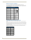
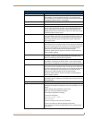
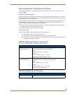
RS-232/422/485 Wiring Specifications
The following table lists the wiring specifications for the RS-232/422/485 connectors (ports 1-6).
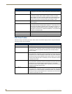
Relay Connections and Wiring
You can connect up to 12 independent external relay devices to the Relay connectors on the NXI (port 7).
Connectors labeled A are for common; B are for output.
Each relay is isolated and normally open.
A metal commoning strip is supplied with each NXI to connect multiple relays.
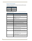
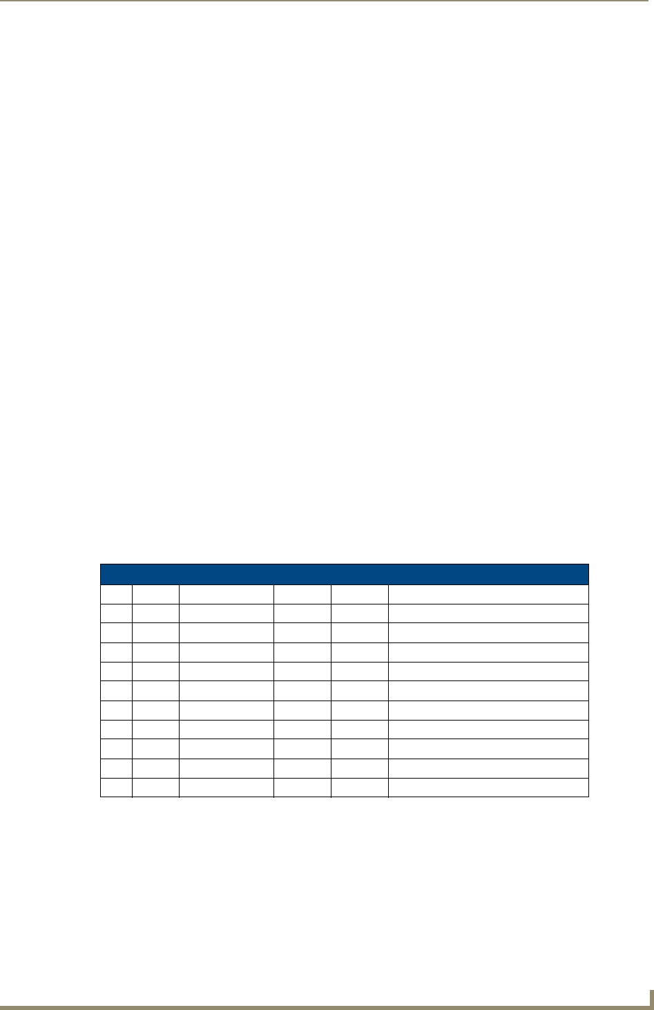
RS-232/422/485 Wiring Specifications
Pin Signal Function RS-232 RS-422 RS-485
1 GND Signal ground X X
2 RXD Receive data X
3 TXD Transmit data X
4 CTS Clear to send X
5 RTS Request to send X
6 TX + Transmit data X X (strap to pin 8)
7 TX - Transmit data X X (strap to pin 9)
8 RX + Receive data X X (strap to pin 6)
9 RX - Receive data X X (strap to pin 7)
10 12 VDC Power optional optional