


8
NXP-CPI16 NetLinx Custom Panel Interface
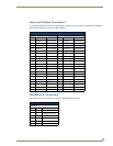
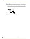
The NXP-CPI16 uses input channels to report user input on the contacts or switches attached to the input
terminals. Output channels are used to turn on the lamp or LED display devices to indicate the button
status to the user.
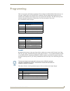
The NXP-CPI16 default mode is STATUS-OFF, and in this mode the programmer cannot poll the NXP-
CPI16 to determine the state of the output channel. This is because in this mode the output and input
channels use the same number assignments. Inputs are sent by the NXP-CPI16 only as input changes.
When set for STATUS-ON mode the output channels are assigned a different channel number than the
input channels. This allows the programmer to monitor the status of an output channel. However the
channel offset must be accommodated in the programming code.
Statements such as this example can be used in a program.
IF[CPI16,25] (* output channel assigned to input channel 9 on P3 connector *)
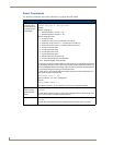
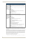
QDIR
Controls the direc-
tion of rotation that
will correspond to a
positive level
increase on the
quadrature inputs.
The default rota-
tion for both
quadrature inputs
is CW (clockwise).
Please note that the actual direction of rotation for a positive level change will depend
upon the phase relationship of the outputs on the quadrature encoder selected. If the
correct phase relationship is not met, it may be necessary to send a CCW (counter-
clockwise) QDIR command to get a positive level change for a clockwise rotation of the
encoder.
Syntax:
‘QDIR <input #> <direction or rotation for a positive level
change>’
Variables:
Where <input#>
1 - Quadrature Input 1
2 - Quadrature Input 2 and <direction of rotation for a positive level change>
CW - Clockwise rotation
CCW - Counter-Clockwise rotation
Example:
SEND_COMMAND ‘QDIR 2 CCW’
The quadrature input 2 is set for counter-clockwise rotation.
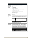
QRATE
Sets the number of
pulses that must
be seen on the
quadrature input in
a given direction in
order to reach the
maximum attain-
able level.
Syntax:
‘QRATE <input #> <# of pulses that represent the maximum level
allowed>’
Variables:
Where <input #>
1 - Quadrature Input 1
2 - Quadrature Input 2
and <# of pulses that represent the maximum level allowed>
0-32,767
This number should be calculated as follows:
Pulses = <pulses/rotation> x <# of rotations to reach maximum level>
The default for Pulses is 24.
Example:
Pulses/rotation = 50 (get from encoder data sheet)
# of rotations desired to reach max. level = 2
Therefore, the equation reads: 50 x 2 = 100.
This value will be used to scale the level reported to the NetLinx master as follows:
level change = (<maximum level> / <Pulses>) x <current pulse count>
Example:
SEND_COMMAND ‘QRATE 1 100’
The full range of quadrature input 1 is set for 100 pulses from the encoder.