


3
NXP-CPI16 NetLinx Custom Panel Interface
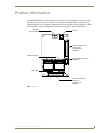
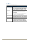
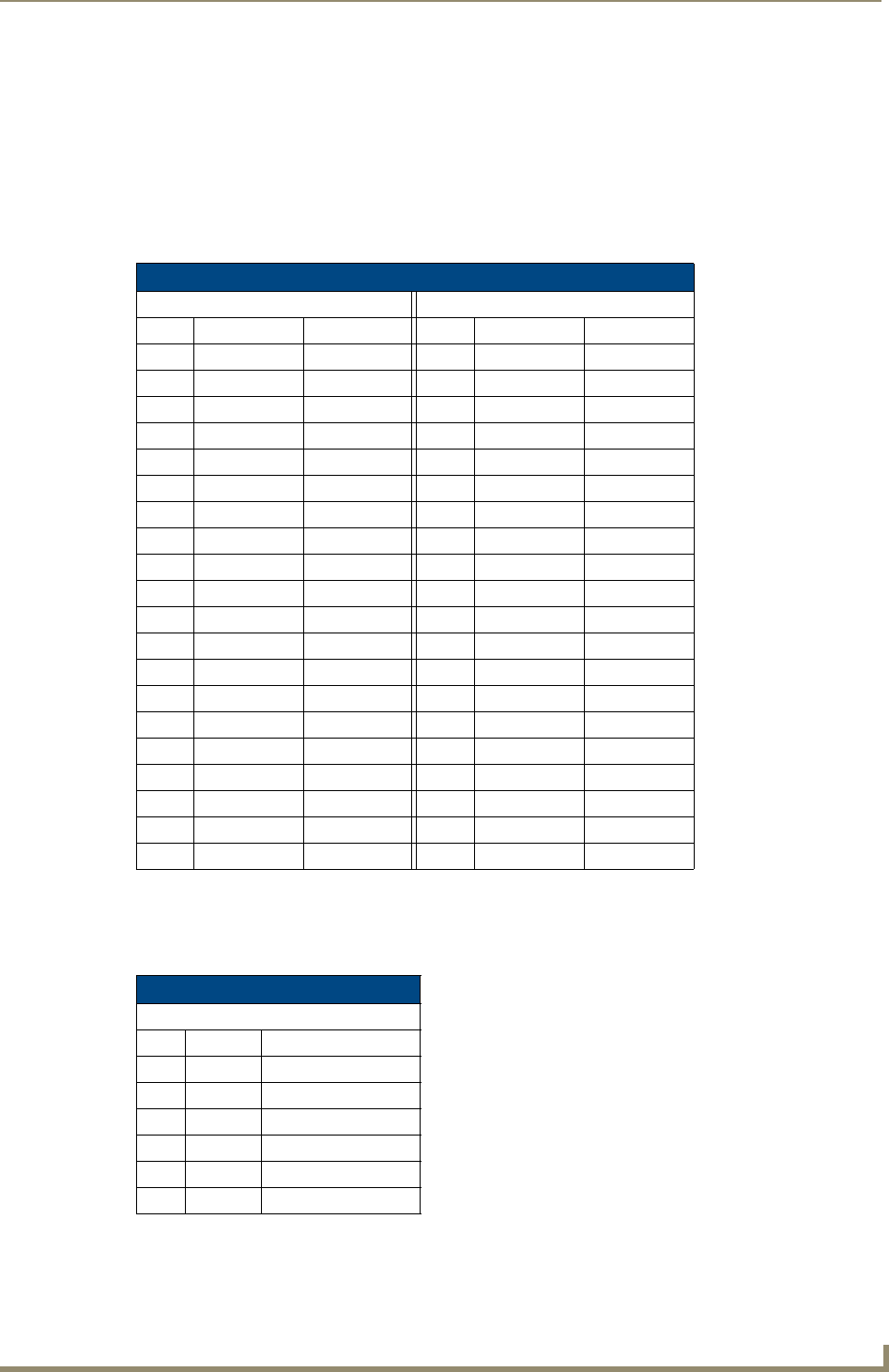
Input and Output Connectors
To install the NXP-CPI16, connect ribbon cables or a PC board to one or more of the headers. The table
below shows the pinouts for the two 20-pin headers.
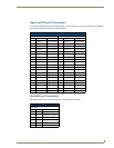
Quadrature Connectors
The table below lists the connector pinouts for the quadrature connector.
I/O Connector Pinouts
Header 1 Header 2
Pin Signal Function Pin Signal Function
1 Output 1 OC to Ground 1 Output 9 OC to Ground
2 Output 2 OC to Ground 2 Output10 OC to Ground
3 Output 3 OC to Ground 3 Output 11 OC to Ground
4 Output 4 OC to Ground 4 Output 12 OC to Ground
5 Output 5 OC to Ground 5 Output 13 OC to Ground
6 Output 6 OC to Ground 6 Output 14 OC to Ground
7 Output 7 OC to Ground 7 Output 15 OC to Ground
8 Output 8 OC to Ground 8 Output 16 OC to Ground
9 Ground Signal Ground 9 Ground Signal Ground
10 Power Power Supply 10 Power Power Supply
11 Ground Signal Ground 11 Ground Signal Ground
12 Ground Signal Ground 12 Ground Signal Ground
13 Input 1 Logic Input 13 Input 9 Logic Input
14 Input 2 Logic Input 14 Input 10 Logic Input
15 Input 3 Logic Input 15 Input 11 Logic Input
16 Input 4 Logic Input 16 Input 12 Logic Input
17 Input 5 Logic Input 17 Input 13 Logic Input
18 Input 6 Logic Input 18 Input 14 Logic Input
19 Input 7 Logic Input 19 Input 15 Logic Input
20 Input 8 Logic Input 20 Input 16 Logic Input
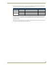
Quadrature Connector Pinouts
Header 3
Pin Signal Function
1 Ground Signal ground
2 1A Encoder # 1, Input A
3 1B Encoder # 1, Input B
4 2A Encoder # 2, Input A
5 2B Encoder # 2, Input B
6 +5 V Encoder power