


2
NXP-CPI16 NetLinx Custom Panel Interface
Specifications
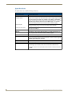
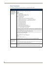
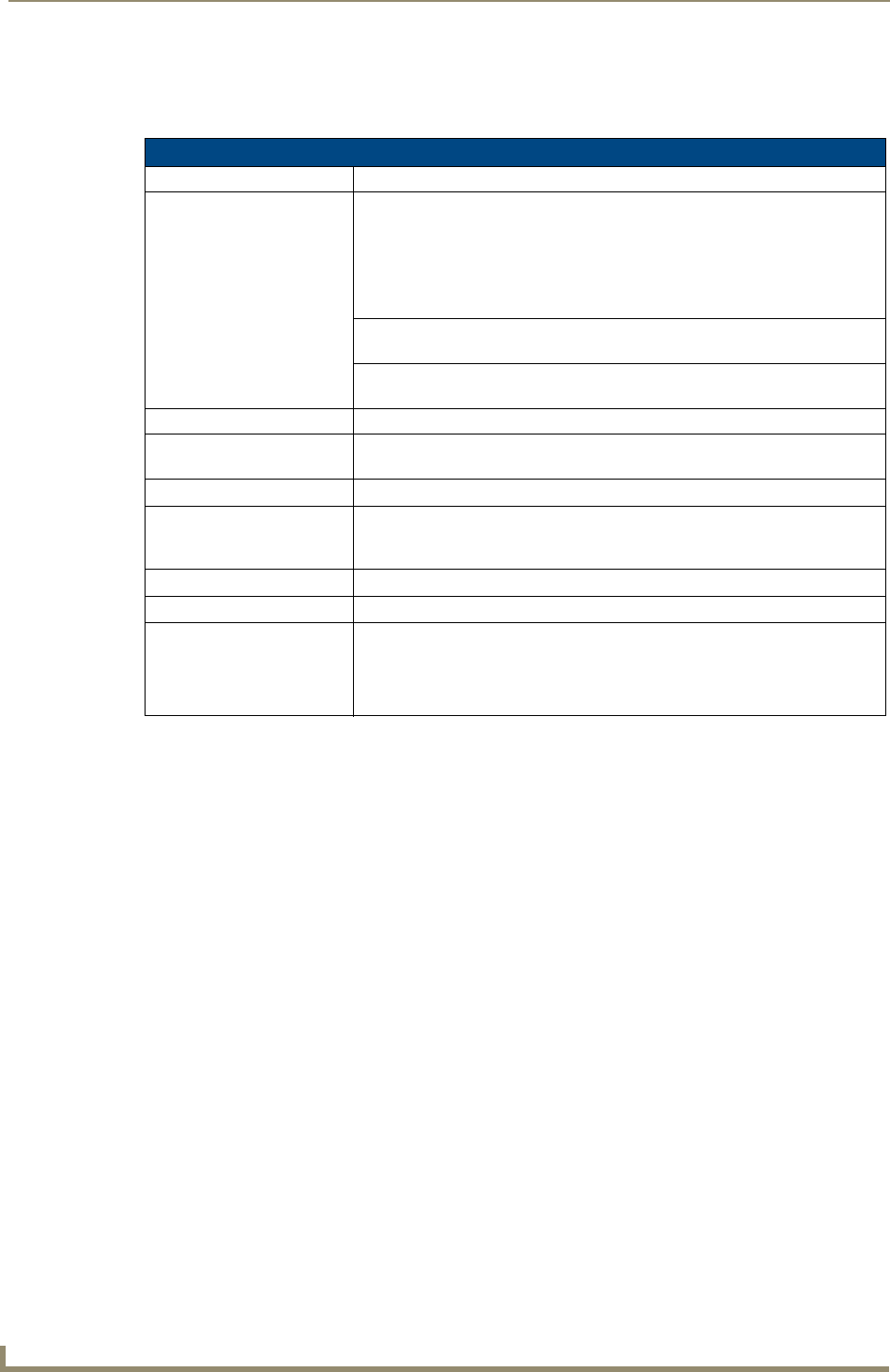
The table below lists the NXP-CPI16 specifications.
NXP-CPI16 Specifications
Power Requirement 12 VDC (300 mA max.)
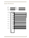
Input Connectors:
Indicator Power Two-pin 3.5 mm captive-wire. This connector is used to supply a higher voltage
and more current to the power pins of Header 1 and Header 2. The external
supply connected to the two-pin captive-wire must be greater than +12 V. If the
external supply voltage is less than that, the ICSNet supply (+12 V) will be
used for the Power pin of the I/O connectors (not the external supply).
Closure Inputs 16 closure inputs activated with a GND or TTL Low (< 0.8 V). Inputs are sam-
pled approximately every 10 msec and are debounced in software.
Rotary Encoder Inputs 2 quadrature inputs on a 2 x 3 header with a +5 V supply pin (supplying up to
100 mA) and a GND pin.
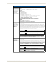
ICSNet 2 RJ-45 connectors for ICSNet connection
ID Button Generates an event from the CPI16 to allow you to assign new Device num-
bers, using ID mode in the NetLinx Studio software program.
LED ICSP status indicator (green)
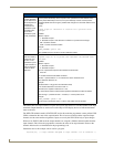
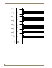
Open Collector Outputs 16 open-collector outputs, acting as a switch to ground, up to 100 mA. Outputs
can be connected to voltages ranging between 0 V and +28 V. Each output is
updated approximately every 10 msec.
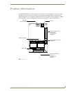
Dimensions (HWD) 2.75" x 1.75" x 0.062" (69.85 mm x 44.45 mm x 1.557 mm)
Weight 8.10 oz (229.6 g)
Accessories • 6-pin header with 3 feet (0.91 m) of ribbon cable
• Two mating 20-pin headers, each with 3 feet of ribbon cable attached
• One green 2-pin 3.5 mm pitch captive wire connector for external indicator
power.