


3
2. Line up your motherboard with the standoff holes, and determine which ones line up and
remember where they are. Not all motherboards will match with all of the provided screw
holes, and this is not necessary for proper functionality. (In other words there will likely be
extra holes.) Some standoffs may be pre-installed for your convenience.
3. Lift up and remove your motherboard.
4. Screw in the brass standoffs to the threaded holes that line up with your motherboard’s
mounting holes.
5. Place your motherboard on the brass standoffs.
6. Mount your motherboard on the standoffs with the provided Phillips-head screws. Your moth-
erboard is now installed.
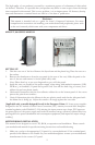
POWER/LED CONNECTIONS
The power supply is an ATX12V form factor power supply. It has a single 24-pin Main Power
Connector, and a 4-pin +12V Power Connector for the motherboard. It is backwards compatible to
previous ATX form factor power supplies. If your motherboard does not support the +12V 4-pin
Power Connector, you can still use this power supply. It also comes with three 4-pin Peripheral
Power Connectors, one SATA Power Connector and one 4-pin Floppy Drive Power Connector for
your drives.
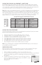
CONNECTING THE USB PORTS
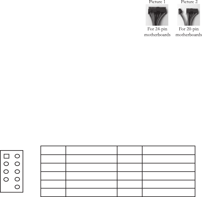
You will fi nd a single 10-pin connector on a cable attached to the front USB ports. This is an Intel
standard connector which is keyed so that it can’t be accidentally reversed as long as it is connected
to a proper Intel standard motherboard header. Connect the 10-pin connector to your motherboard
headers so that the blocked pin fi ts over the missing header pin.
Note: Please check your motherboard manual for your USB header pin layout and make sure it
matches the attached table. If it does not match this Intel standard, please call Antec customer
support at (800) 22ANTEC (North America) or at +31 (0) 10 462-2060 (Europe) to buy a USB
adapter. This adapter will allow you to connect the front USB to your motherboard on a pin-by-pin
basis.
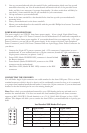
Intel Standard USB Header Pin Layout
Pin Signal Names Pin Signal Names
1 USB Power 1 2 USB Power 2
3 Negative Signal 1 4 Negative Signal 2
5 Positive Signal 1 6 Positive Signal 2
7 Ground 1 8 Ground 2
9 Key (No Connection) 10 Empty Pin
12
109
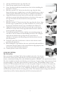
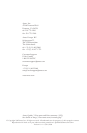
1. Connect the 24-pin ATX power connector (and +12V connectors if appropriate) to your
motherboard. If your motherboard uses a 20-pin connector; detach the 4-pin attachment on
24-pin power connector (see picture 1 and 2).
2. Power LED (labeled POWER LED) connector is located behind
the Reset connector.
3. Power Switch (labeled POWER SW) connects to the PWR
connector on the motherboard.
4. Hard Drive LED (labeled H.D.D. LED) connects to the IDE
connector.