


4
CONNECTING THE IEEE 1394 (FIREWIRE
®
, I.LINK
®
) PORT
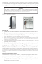
You will fi nd a single 10-pin connector on a cable attached to the front IEEE 1394 connection.
This is an Intel standard connector, which is keyed so that it can’t be accidentally reversed as long
as it is connected to a proper Intel standard motherboard header. Connect the 10-pin connector to
your motherboard header so that the blocked pin fi ts over the missing header pin.
Note: Please check your motherboard manual for your IEEE 1394 header pin layout and make sure
it matches the attached table. If you intend to connect the front FireWire port to an IEEE 1394
add-on card that comes with an external-type IEEE1394 connector, please call Antec customer ser-
vice at (800) 22ANTEC (North America) or +31 (0) 10 462-2060 (Europe) to buy an adapter. This
adapter will allow you to connect the front IEEE 1394 port to the external-type connector.
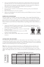
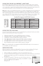
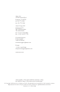
Standard Pin Assignment for IEEE 1394 Connector
12
109
Pin Signal Names Pin Signal Names
1 TPA + 2 TPA -
3 Ground 4 Ground
5 TPB + 6 TPB -
7 +12V (Fused) 8 +12V (Fused)
9 Key (No pin) 10 Ground
CONNECTING THE AUDIO PORTS
Locate the internal audio connectors from your motherboard or sound card. Consult your mother-
board or sound card manual for the pin-out positions.
1. Microphone Signal Pin: Connect the MIC-IN connector to this pin.
2. Microphone Power: Connect the MIC-POWER connector to this pin.
3. Ground Pin: Connect the GROUND connector to this pin.
4. Front Right Speaker Out Pin: Connect the R-OUT connector to this pin.
5. Front Right Speaker Out Pin: Connect the L-OUT connector to this pin.
6. Rear Right Speaker Out Pin: Connect the R-RET connector to this pin.
7. Rear Left Speaker Out Pin: Connect L-RET connector to this pin.
Note: If your motherboard is not equipped with REAR SPEAKER output, it is not necessary to
use the R-RET and L-RET connectors.
DRIVE INSTALLATION
Minuet incorporates a rapid-release Flip Up Drive Cage for easy drive installation. The Cage in-
cludes three drive bays: one external 5.25”, one external 3.5”, and one internal 3.5”.
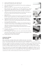
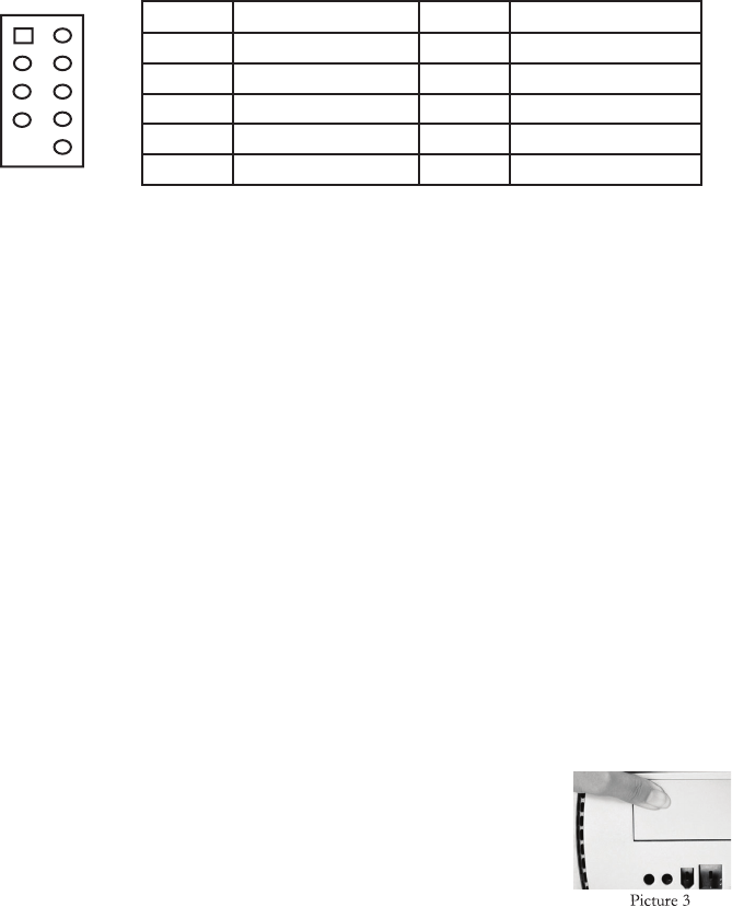
1. Before installing the external drives, remove the external drive bay covers.
a. To remove the external 5.25” drive bay cover, face the front of the case and use your left hand
thumb to press fi rmly on the LEFT or outside edge of the left bay cover to release it.
(See picture 3)
b. To remove the external 3.5” drive bay cover, face the front of the case
and use your right hand thumb to press fi rmly on the RIGHT or outside
edge of the right bay cover to release it.
(See picture 4)