


4
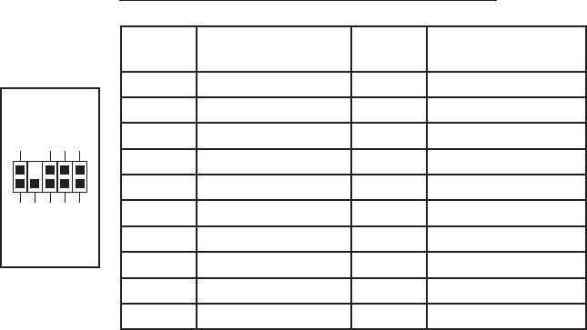
Pin Assignment for Audio Ports (HDA and AC’97)
Locate the internal audio connectors from your motherboard or sound card.
Consult your motherboard or sound card manual for the pin-out positions.
3.5” Device Installation
With the front bezel facing you, swing the front door out. It can swing 270 degrees
so the door will parallel with the side of the case. You will see there are four 5.25”
and one 3.5” external drive bays. Inside the case there are two 3.5” drive cages,
which can house up to six hard drives. Note: We recommend using the lower HDD
cage to get the maximum possible cooling and quiet computing.
The Upper HDD Installation.
1. Remove the thumbscrew holding the upper HDD cage.
2. Pull the HDD cage from its position by pulling the ring towards you.
3. There are two HDD trays inside the cage. Squeeze the metal clips on each
side of the tray and slide the tray out.
4. Mount your hard drive into the drive tray with the special screws provided.
dampening ability of the silicone grommets. Note: Do not over-tighten the
screws as this will reduce the vibration and noise-dampening ability of the
rubber grommets. Always mount the HDD with the thicker side of the silicone
grommets facing up.
5. Slide and lock the tray back into the case.
6. Repeat the same procedure for other devices as necessary.
7. Connect 4-pin molex or SATA power connectors on the power supply to the
power connectors on each of the devices.
8. Slide the cage back to the case and fasten the thumbscrew.
The Lower HDD Installation.
1. Remove the thumbscrew holding the lower HDD cage.
2. Pull the HDD cage from its position by pulling the ring towards you.
3. You can mount four hard drives vertically inside the cage.
4. Mount your hard drive into the drive cage with the special screws provided.
Note: Do not over-tighten the screws as this will reduce the vibration and
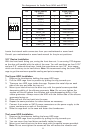
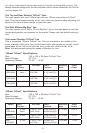
Pin Signal Names
(HDA)
Pin Signal Names
(AC’97)
1 MIC2 L 1 MIC In
2 AGND 2 GND
3 MIC2 R 3 MIC Power
4 AVCC 4 NC
5 FRO-R 5 Line Out (R)
6 MIC2_JD 6 Line Out (R)
7 F_IO_SEN 7 NC
8 Key (no pin) 8 Key (no pin)
9 FRO-L 9 Line Out (L)
10 LINE2_JD 10 Line Out (L)
1
2
3579
46
10