3
©1994 - INLINE, INC. IN1222 / IN1422 / IN1510 / IN1710 OPERATIONS MANUAL - REV. 2 12/04/99
OUTPUT COMPATIBILITY
All INLINE decoders and doublers offer a high quality 24-bit output video signal. The units may be set
to any of the following output signal formats as required: RGBS, RGBHV, and RsGsBs (for information
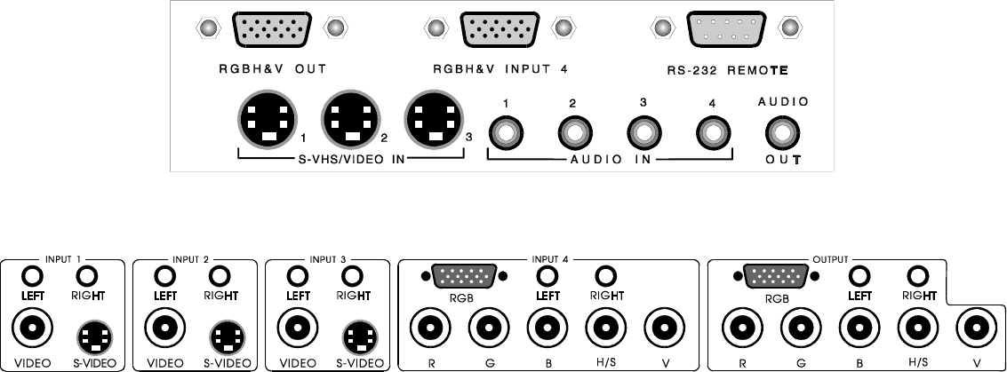
on changing output sync formats see page 14). The RGB Video and audio output connections are shown
in the diagrams on pages 3, 6 & 7.
The IN1510/IN1710 and the IN1222/IN1422 in interlaced (non-doubling) mode output a signal with the
same scan rate as the input signal. The decoded signal is compatible with many RGB monitors, video
projectors with RGB inputs and will also operate with many LCD projection panels.
The IN1222/IN1422 in non-interlaced (doubling) mode output a signal at twice the original scan rate.
RGB monitors, data projectors, and LCD panels capable of displaying a 31.5 KHz VGA signal (640 x
480 mode) can be used to display the decoded/doubled output signal.
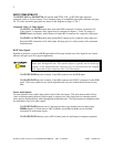
RGB Video Output
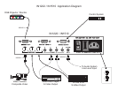
The IN1222/IN1510 feature a 15-pin HD female output connector. One IN9045 output adapter
cable (15-pin HD male to 5-BNC male, 12’ long) is included with each unit.
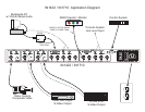
The IN1422/IN1710 feature both a 15-pin HD female connector and 5 female BNC connectors.
The two RGB outputs are wired in parallel and may not be used simultaneously.
Stereo Audio Output
All units route the selected audio signals to the output connector as an unbalanced line level signal. The
output voltage gain varies according to the VOLUME setting for the selected input.
The IN1222/IN1510 feature a 3.5 mm ring-tip-sleeve type female jack for audio output. An
IN9090 adapter (3.5 mm male to 2-RCA female) is included with the unit to facilitate connection
to other audio devices.
The IN1422/IN1710 feature a pair of RCA female jacks for the stereo audio output.
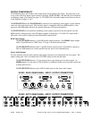
IN1222 / IN1510 REAR PANEL - INPUT / OUTPUT CONNECTORS
IN1422 / IN1710 REAR PANEL - INPUT / OUTPUT CONNECTORS


