


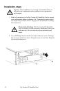
8
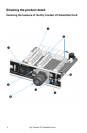
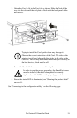
Dry Contact I/O SmartSlot Card
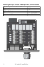
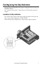
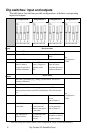
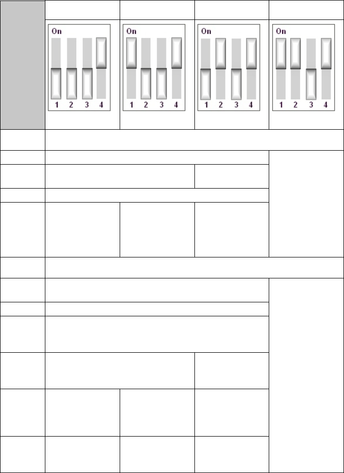
Dip switches: input and outputs
The table below lists the four possible configurations, with their corresponding
inputs and outputs.
* With this setup (the factory default), the Configuration Utility is used automatically.
Configuration 1 Configuration 2 Configuration 3 Configuration 4*
OFF-OFF-OFF-ON ON-OFF-OFF-ON OFF-ON-OFF-ON ON-ON-OFF-ON
Inputs
Device Actions
1 Turn the UPS on.
See
Configuration
Utility
2 Turn the UPS off. Turn the UPS off
safely.
3 Start UPS self-test.
4 Shut down the UPS
when on battery
except for self-test or
runtime calibration.
Put the UPS in
bypass, if bypass is
available on the
UPS.
Shut down the UPS
when on battery
except for self-test or
runtime calibration.
Outputs
Device State
1 The UPS is on-battery (e.g., during a power failure, self-test, or
runtime calibration).
See
Configuration
Utility
2 The UPS has a low battery.
3
The protected load is not receiving power from the UPS or
communication between the UPS and the Relay I/O Card has been
lost.
4 Replace the UPS battery.
UPS commanded to
turn on
(echo of Input 1).
5
The UPS is
overloaded.
The UPS is in bypass
by selection from
software, front panel,
or rear panel.
UPS commanded to
turn off gracefully
(echo of Input 2).
6
Any UPS fault or
self-test failure.
Any UPS fault, self-
test failure, or
overload.
Any UPS fault, self-
test failure, overload,
or replace battery