


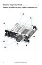
Dry Contact I/O SmartSlot Card
5
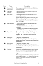
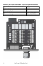
Item Name Description
Universal I/O
ports 1 and 2
These support the AP9335T/ TH and AP9810 dry
contact accessories
USB cable
connector
Connecting this to your PC enables usage of the
Configuration Utility.
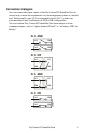
Reset button Use an appropriately sized, non-metallic tool to
press the Reset button.
Holding the button for 5 seconds reboots the Card.
Holding the button for 25 seconds resets the Card to
the factory defaults. (The status light flashes green
when you do this).
Status indicator • SOLID GREEN indicates communications and
operations are fine
•
FLASHING GREEN indicates the Card is
initializing
•
FLASHING RED indicates a communication fault
•
SOLID RED indicates a non-operational fault
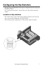
Dip switches These are located near the back of the front panel on
the right-hand side. See the “Location of dip
switches” and “Configuring the Dip Switches”
sections.
Output relay
terminals
Connections for alarm outputs.
See “Itemizing the input contact and output relay
terminal blocks” and “Ratings for input contacts and
output relays” .
Input contact
terminals
Connections for control inputs.
See “Itemizing the input contact and output relay
terminal blocks” and “Ratings for input contacts and
output relays” .
Cord grip Supports the cabling that is used to control external
devices, or to connect up external switches. The
bare wires connect to the terminal blocks on the
Card.
The cord grip is plastic and can secure a single cord
with a diameter range of 5.8 – 10mm. This limits the
number of conductors (inside the cord) and the
power ratings.